
Cloth drying device

A cloth drying and hot air technology, applied in drying, drying machine, drying gas arrangement, etc., can solve problems such as waste of energy, damage to cloth tissue, and large heating area

Inactive Publication Date: 2015-02-11
常州市嘉翔纺织印染有限公司
View PDF0 Cites 40 Cited by
  • Summary
  • Abstract
  • Description
  • Claims
  • Application Information

AI Technical Summary

Problems solved by technology

[0002] In the fabric production process, the fabric needs to be cleaned, printed and dyed, dried and other processes. Drying the fabric is an indispensable process in the fabric production. The existing drying equipment mainly includes a square oven, and the electric heating in the oven The fabric passes through the oven, and the heat generated by the electric heater is used to heat and dry the fabric. In this structure, due to the use of a square oven, the area to be heated in the oven is relatively large, and the power of the electric heater needs to be increased. Waste of energy; in addition, the electric heater directly heats and dries the cloth in the oven, which is easy to cause damage to the tissue of the cloth and reduce the quality of the cloth

Method used


Image

  • Cloth drying device

Examples


Embodiment Construction

[0011] The present invention will be further described below in conjunction with the accompanying drawings and specific embodiments.

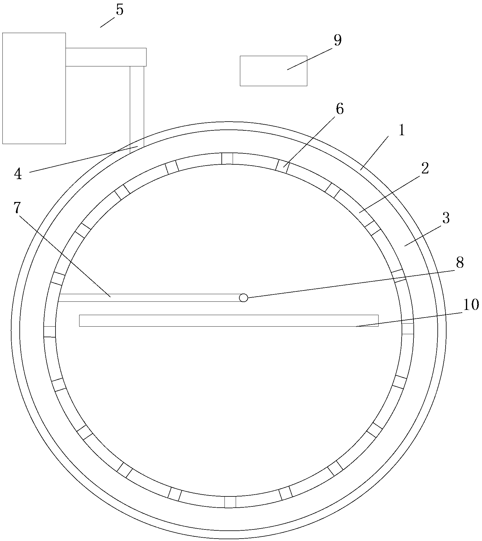
[0012] see figure 1 , a cloth drying device, comprising a first cylinder body 1 and a second cylinder body 2 with a circular cross section, the second cylinder body is located in the first cylinder body, and a closed cylinder is formed between the inner wall of the first cylinder body and the outer wall of the second cylinder body The hot gas interlayer 3 is provided with a heat-sending through hole 4 communicating with the hot gas interlayer on the first cylinder; the heat-sending through hole is communicated with the external hot gas delivery device 5; the second cylinder is provided with several communicating hot gas interlayers and The hot gas passage hole 6 in the inner cavity of the second cylinder. The circular through hole of the hot gas through hole has a diameter of 1mm, 2mm, 3mm, 4mm, 5mm, 6mm, 7mm, 8mm, 9mm, 10mm; The support 7 is...


PUM

PropertyMeasurementUnit
Diameteraaaaaaaaaa
Diameteraaaaaaaaaa

Abstract

The invention relates to the technical field of textile, in particular to a cloth drying device. The cloth drying device comprises a first cylinder and a second cylinder with the sections being in circular shapes; the second cylinder is arranged inside the first cylinder; a sealed hot gas interlayer is formed between the internal wall of the first cylinder and the external wall of the second cylinder; a heat sending through hole which is communicated with the hot gas interlayer is formed in the first cylinder; a plurality of hot air through holes which are communicated with the hot air interlayer are formed in the second cylinder. According to the cloth drying device, the space required to be heated is reduced and energy is saved due to the circular internal chamber; damage of cloth tissues is avoided and the cloth quality is guaranteed due to the facts that externally arranged hot air is conveyed to the hot air interlayer and is diffused to the internal chamber of the second cylinder to dry and heat cloth passing through the internal chamber of the second cylinder, and direct heating of the cloth through an electric heater is avoided.

Description

technical field [0001] The invention relates to the technical field of textiles, in particular to a cloth drying device. Background technique [0002] In the fabric production process, the fabric needs to be cleaned, printed and dyed, dried and other processes. Drying the fabric is an indispensable process in the fabric production. The existing drying equipment mainly includes a square oven, and the electric heating in the oven The fabric passes through the oven, and the heat generated by the electric heater is used to heat and dry the fabric. In this structure, due to the use of a square oven, the area to be heated in the oven is relatively large, and the power of the electric heater needs to be increased. Waste of energy; In addition, the electric heater directly heats and dries the cloth in the oven, which is easy to cause damage to the tissue of the cloth and reduces the quality of the cloth. Contents of the invention [0003] In view of the above technical problems, ...

Claims


Application Information

Patent Timeline
IPC IPC(8): F26B13/10F26B21/10
Inventor 吴大方
Owner 常州市嘉翔纺织印染有限公司
Learn More