Core for wire-wound electronic component, wire-wound electronic component, and common mode choke coil

An electronic component, wire-wound technology, applied in the direction of transformer/inductor parts, electrical components, transformer/inductor magnetic core, etc., can solve problems such as disconnection, and achieve the effect of suppressing disconnection

Active Publication Date: 2015-02-11
MURATA MFG CO LTD
View PDF4 Cites 17 Cited by
  • Summary
  • Abstract
  • Description
  • Claims
  • Application Information

AI Technical Summary

Problems solved by technology

Therefore, when a common mode choke coil including the core is mounted on a circuit board, if a foreign object is caught between the flange portion and the circuit board, the portion passing through the groove in the coil may be turned toward the circuit board. The bottom of the groove is pressed and broken

Method used


Image

  • Core for wire-wound electronic component, wire-wound electronic component, and common mode choke coil
  • Core for wire-wound electronic component, wire-wound electronic component, and common mode choke coil
  • Core for wire-wound electronic component, wire-wound electronic component, and common mode choke coil

Examples


Embodiment Construction

[0025] (For the structure of wire-wound electronic components, refer to figure 1 )

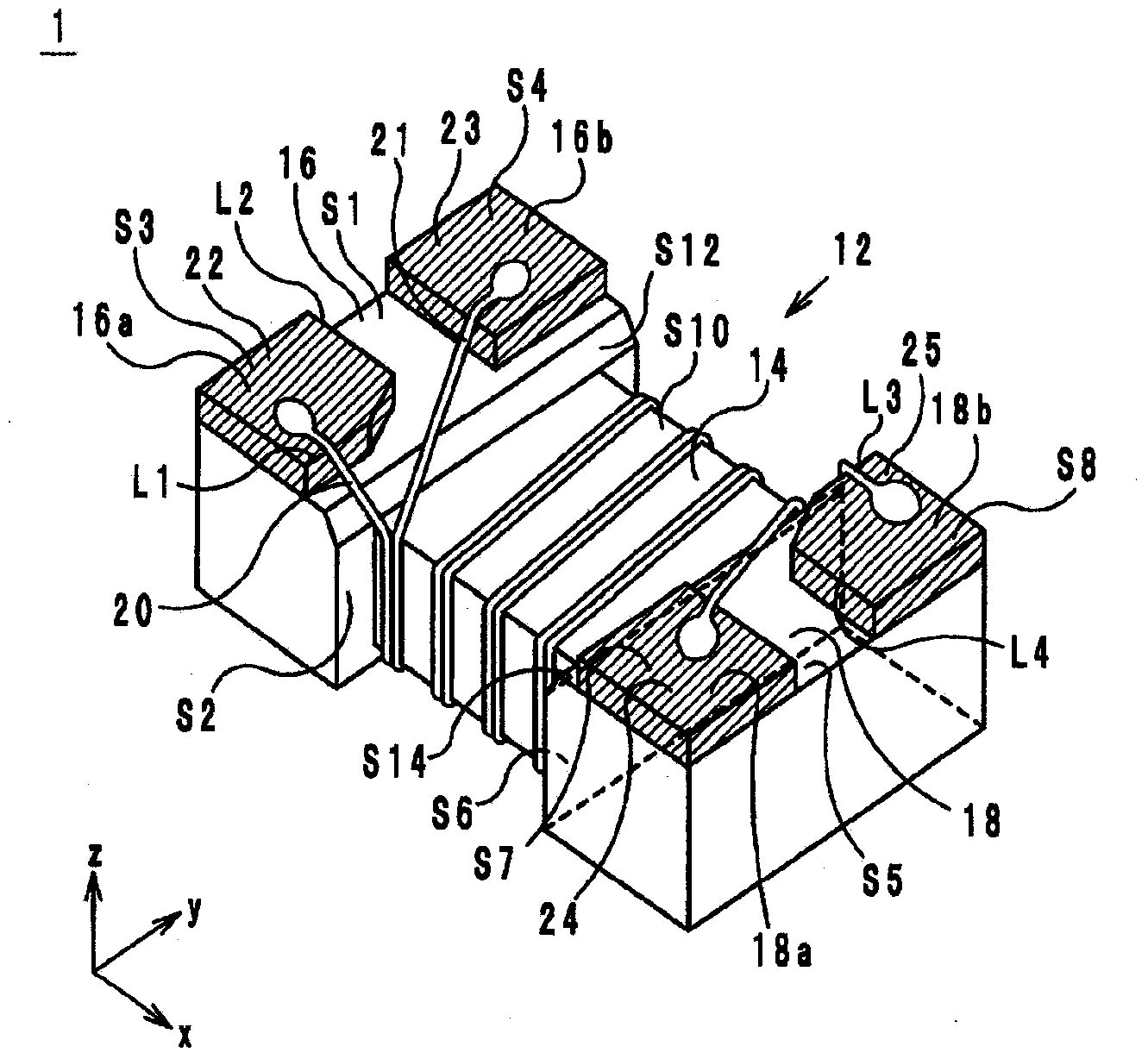
[0026] A wire-wound electronic component 1 according to an embodiment will be described with reference to the drawings. Hereinafter, the direction in which the core portion 14 extends is defined as the x-axis direction. In addition, when viewed from the x-axis direction, the direction along the long side of the flange portion 16 is defined as the y-axis direction, and the direction along the short side of the flange portion 16 is defined as the z-axis direction. Wherein, the x-axis, y-axis and z-axis are orthogonal to each other.

[0027] Such as figure 1 As shown, the wire-wound electronic component 1 includes a core 12 , coils 20 and 21 , and external electrodes 22 to 25 .

[0028] The core 12 is made of, for example, a magnetic material such as ferrite or an insulating material such as alumina, and includes a winding core portion 14 and flange portions 16 and 18 .

[0029] The winding ...


PUM

PropertyMeasurementUnit
diameteraaaaaaaaaa

Abstract

A core for a wire-wound electronic component. The core has a winding base to be wound with a wire, and flanges located at both ends of the winding base in an extending direction of the winding base. The flanges protrude from the winding base in a first direction perpendicular to the extending direction. Each of the flanges has a plurality of protrusions on a first surface at a side of the flange in the first direction. An inclined surface is provided to extend from the first surface of each of the flanges to a second surface of the winding base at a side of the winding base in the first direction.

Description

technical field [0001] The present invention relates to a core of a wire-wound electronic component, a wire-wound electronic component, and a common mode choke coil, and relates in detail to the shape of a flange portion of the core of a wire-wound electronic component. Background technique [0002] As a core of a conventional wire-wound electronic component, a core of a common mode choke coil described in Patent Document 1 is known. Flange portions are provided at both ends of the winding core portion of such a core, and each flange portion is divided into two by grooves parallel to the extending direction of the winding core portion. Furthermore, external electrodes are respectively provided in the above-mentioned parts. [0003] In addition, the coil wound on the core passes through the groove on the route from the winding core portion to the external electrode. In this way, the portion passing through the groove in the coil is in a suspended state without being in cont...

Claims


Application Information

Patent Timeline
Patent Type & Authority Applications(China)
IPC IPC(8): H01F27/24H01F17/04H01F27/29
CPCB65H75/06H01F27/29H01F17/04H01F27/2828H01F27/292H01F27/28
Inventor 坂东政博青木隆博
Owner MURATA MFG CO LTD
Why Eureka
Try Eureka