
LED driving apparatus and illuminating device

A technology of LED driving and LED light source, applied in lighting devices, electric lamp circuit layout, light source and other directions, can solve the problem of difficulty in ensuring illuminance, and achieve the effect of suppressing the decrease of illuminance

Active Publication Date: 2015-02-11
PANASONIC INTELLECTUAL PROPERTY MANAGEMENT CO LTD
View PDF4 Cites 1 Cited by
  • Summary
  • Abstract
  • Description
  • Claims
  • Application Information

AI Technical Summary

Problems solved by technology

[0004] In addition, in an LED drive device that drives a plurality of LED light sources like the device described in Document 1, there is a case in which when an abnormality occurs in a certain LED light source, if only the driving of the LED light source is stopped (the LED light source goes out) will produce bad condition
For example, when an LED light source is used as a light source for road lighting or tunnel lighting, it may be difficult to ensure the required minimum illuminance because some of the LED light sources are turned off.

Method used


Image

  • LED driving apparatus and illuminating device
  • LED driving apparatus and illuminating device
  • LED driving apparatus and illuminating device

Examples


Embodiment Construction

[0021] Hereinafter, the LED driving device in the embodiment according to the present invention will be described in detail with reference to the drawings.

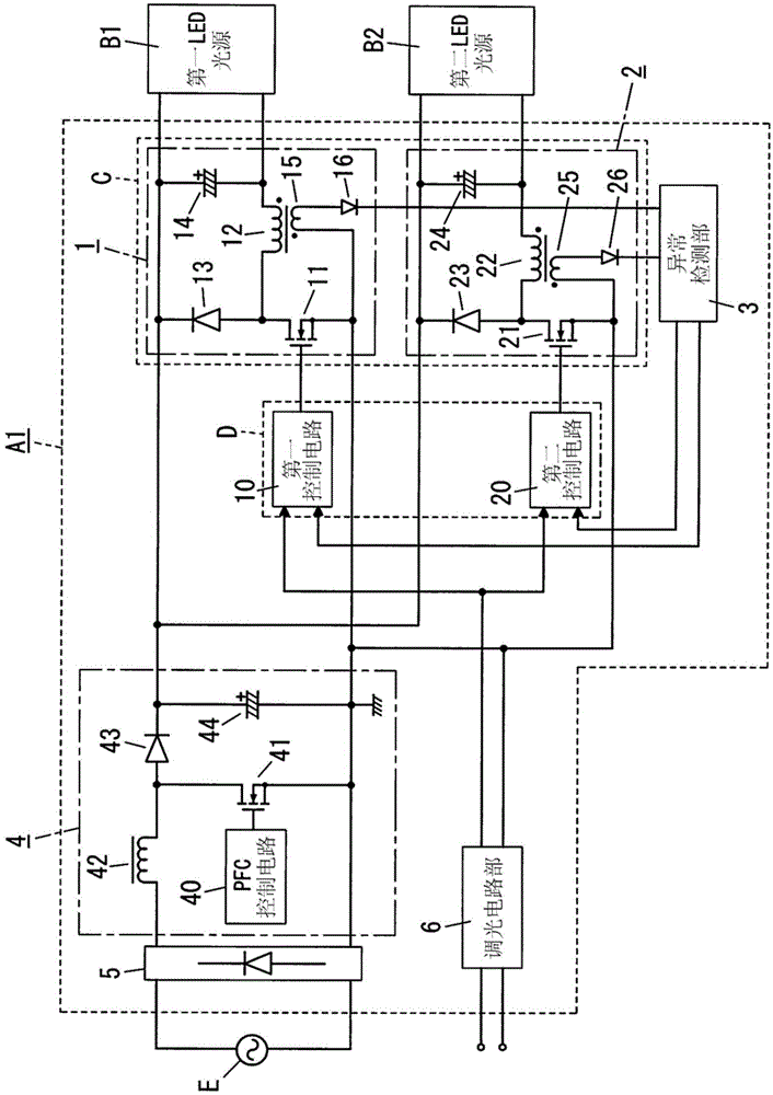
[0022] The LED driving device A1 of this embodiment is as figure 1 As shown, it includes an adjustment unit C, an abnormality detection unit 3 , an AC / DC conversion unit 4 , a full-wave rectifier 5 , a control unit D, a dimming circuit unit 6 , and the like. exist figure 1 In the example of , the adjustment unit C is composed of a DC / DC conversion unit 1 and a DC / DC conversion unit 2 . The AC / DC conversion unit 4 is composed of a power factor correction (Power Factor Correction: power factor correction) circuit.

[0023] The full-wave rectifier 5 is composed of a diode bridge, and performs full-wave rectification of the AC voltage and AC current supplied from the AC power supply E to output to the AC / DC converter 4 .

[0024] The AC / DC converter 4 is configured to convert AC power, which is input power, into DC power. ...


PUM


Abstract

[Problem] To provide an LED driving device and a lighting apparatus. LED driving device is configured by the input power into DC power and DC power supplied to the plurality of LED light source side, thereby driving a plurality of LED light sources. [solution] The LED driving device comprises: an adjusting unit which respectively adjusts the DC power supply to a plurality of LED light sources, wherein the adjusted DC power supply is employed as outout to the plurality of LED light sources as a respective output; and a control unit being used in a following situation: when abnormality in a part of the plurality of the LED light sources is detected during respective abnormality detection of the LED light sources, the control unit control the adjusting unit to stop outout from the adjusting part to the part and enables rest output to increase from the adjusting unit to the LED light sources.

Description

technical field [0001] The invention relates to an LED driving device and a lighting appliance. Background technique [0002] Japanese Patent Application Publication No. 2011-154841 (hereinafter referred to as "Document 1") discloses an LED lighting device. The device described in Document 1 includes a DC / DC converter, a switching control unit, a PWM (Pulse Width Modulation: pulse width modulation) controller, and an abnormality detection unit. The switching control unit selectively performs switching control on the connection between the two LED light sources and the output end of the DC / DC converter. The PWM controller increases or decreases the output of the DC / DC converter according to the LED light source connected to the output terminal of the DC / DC converter by the switching control unit. The abnormality detection unit detects abnormality (short circuit, no load, etc.) of the two LED light sources, respectively, and stops power supply to the LED light source of whic...

Claims


Application Information

Patent Timeline
Patent Type & Authority Applications(China)
IPC IPC(8): H05B37/02
Inventor 增本进吾上仮屋淳一帆足淳次松井弘毅
Owner PANASONIC INTELLECTUAL PROPERTY MANAGEMENT CO LTD
Learn More