
Generator control device

A technology for control devices and generators, applied in radiological diagnostic equipment control, radiological diagnostic instruments, medical science, etc., to achieve simple distribution, ensure image quality, and reduce maintenance costs

Inactive Publication Date: 2015-02-11
SIEMENS AG
View PDF4 Cites 0 Cited by
  • Summary
  • Abstract
  • Description
  • Claims
  • Application Information

AI Technical Summary

Problems solved by technology

However, this only enables the simplest mode of operation

Method used


Image

  • Generator control device
  • Generator control device
  • Generator control device

Examples


Embodiment Construction

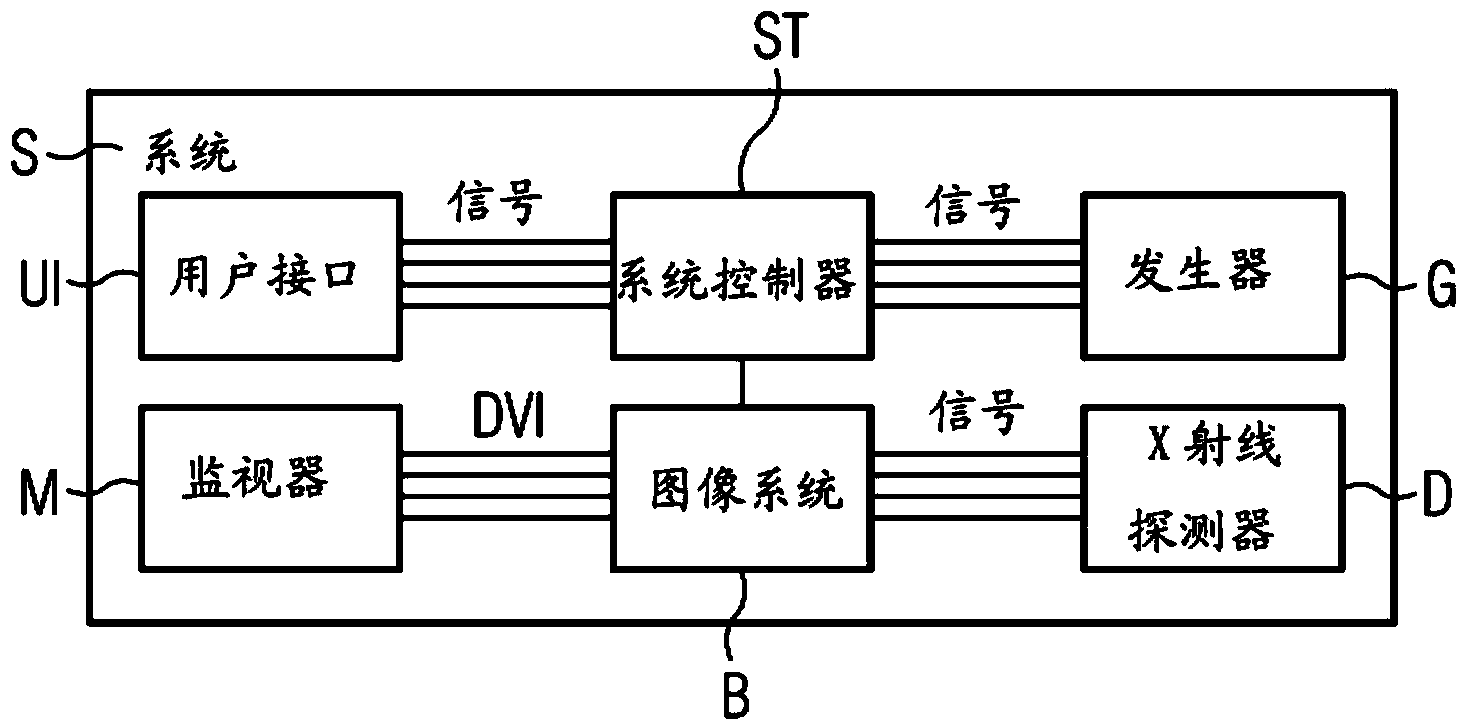
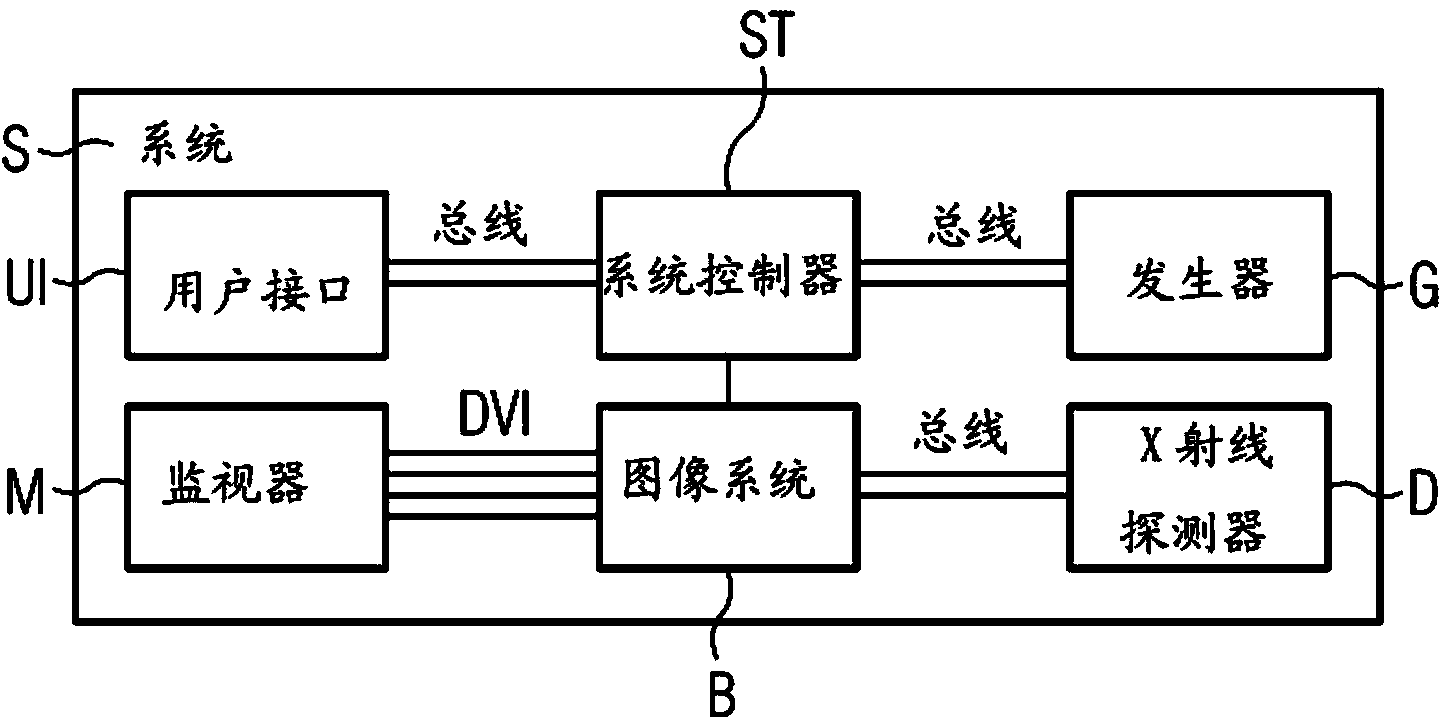
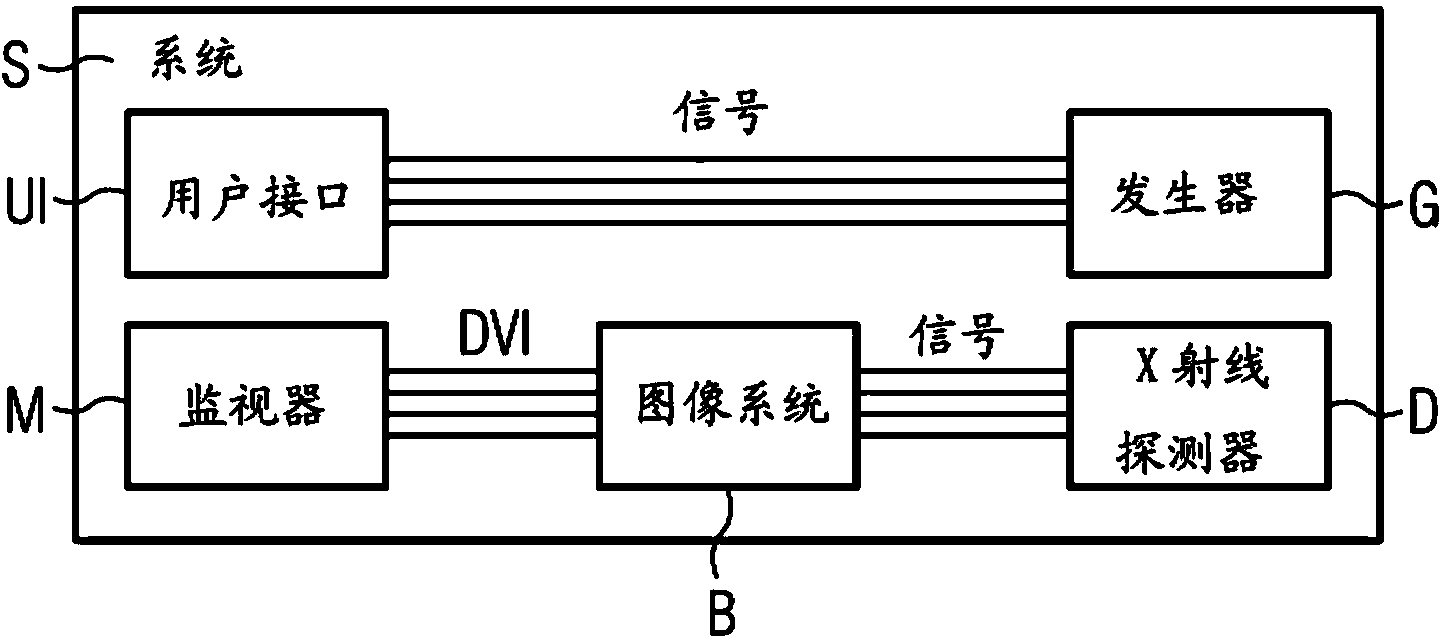
[0037] figure 2 with image 3 A system S or device is shown which has a user interface UI, a generator controller GS and a communication interface K between the user interface and the generator controller GS. It also shows a button T, preferably for radiation triggering, which is connected to the generator controller GS. Alternatively, triggering can also take place via the user interface. exist image 3 In addition, an x-ray detector D is arranged, which can be connected to the generator controller via the bus Bus / Signale and which can communicate with the user interface UI if necessary via a further communication interface K′.

[0038] The communication interfaces K and K' are preferably characterized by radio connections, which are designed wirelessly or cordlessly. Standardized transmission methods such as Bluetooth, DECT, WLAN / WIFI, GSM, 3G, UMTS, HSDPA or 4G and / or LTE and other methods are conceivable for the radio connection. So-called smart devices are conceivab...


PUM


Abstract

A generator control device for a system generating x-radiation, and a corresponding operating method, arrangement and system are provided. The operating method for the generator control device includes providing configuration data for the system that generates the x-radiation via at least one first communication interface. The method also includes receiving at least one signal for triggering generation of the x-radiation via a second communication interface or the first communication interface. The method includes receiving information for displaying image data from a unit receiving the x-radiation, and providing at least one smart device with the information via a further communication interface.

Description

technical field [0001] The invention relates to a generator control device for a system for generating x-ray radiation, as well as a corresponding operating method, device or system. Background technique [0002] The monolithic, closed application structure proved to be extremely inflexible relative to the dynamics of the health services market. It is desirable to be able to gradually introduce the possibility of software modules or hardware modules and thus enable integration in existing IT landscapes (IT-Landschaft). The advantage for the individual is that it gradually leads to new challenges in information processing. An open architecture enables the integration of foreign systems immediately or at a later point in time. [0003] In developing markets, mobile x-ray devices are often in the lower price segment, often only having a very simple user interface for cost reasons. As a result, the user finds it difficult to select the correct operating mode / setting or config...

Claims


Application Information

Patent Timeline
Patent Type & Authority Applications(China)
IPC IPC(8): H05G1/30H04W4/80
CPCH04W4/008H04W4/80A61B6/467A61B6/566A61B6/461A61B6/54A61B6/563A61B6/548A61B6/00H04W4/00H05G1/30
Inventor T.迪普尔G.加姆克H.格尔维泽S.海德M.维格
Owner SIEMENS AG
Learn More