A motorized viscous material dispenser

A dispenser, motorized technology for use in caulking guns

Active Publication Date: 2015-02-11
MEDMIX SWITZERLAND AG
View PDF5 Cites 3 Cited by
  • Summary
  • Abstract
  • Description
  • Claims
  • Application Information

AI Technical Summary

Problems solved by technology

From a manufacturing point of view, the above technique has the disadvantage that, when manufacturing different types of dispensers with different distances between racks or with different numbers of racks, a dedicated drive unit must be manufactured for each type of dispenser

Method used


Image

  • A motorized viscous material dispenser
  • A motorized viscous material dispenser
  • A motorized viscous material dispenser

Examples


Embodiment Construction

[0028] For simplicity, the terms "upper", "lower", "front" and "rear" in the description of the invention are used to describe the interrelationship of the different parts and assemblies of an embodiment of the dispenser according to the invention. Those skilled in the art will recognize that the dispenser will generally be tipped, tipped and turned during use to suit the actual task being performed with the dispenser.

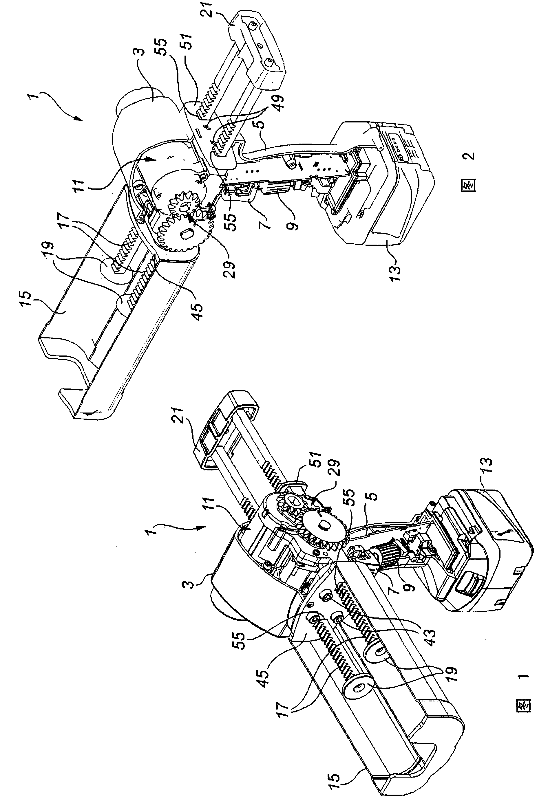
[0029] figure 1 and figure 2 An embodiment of such a motorized viscous material dispenser 1, commonly referred to as a caulking gun, is shown. The caulking gun comprises a housing 3, part of which has been left out to show the internal components, which provides a handle 5 to be grasped by the operator for operating the dispenser to dispense material. At the handle, the dispenser includes a trigger 7 and a speed control dial 9 . The housing 3 houses the drive unit 11, the components of which are also shown in Figure 5 , 6 , 9 in. Attached to the bottom...


PUM


Abstract

A motorized viscous material dispenser (1), especially a caulking gun, comprises a drive unit (11) with a cylindrical pinion gear, a holder (15) attachable to a front side of the drive unit (11) for receiving at least one container containing viscous material, at least one piston (19), and at least one rack (17) meshing with the cylindrical pinion gear to drive said piston (19). A rear piece (51) attachable to a rear side of the drive unit (11) opposite the front side and a guide piece (45) attachable to the front side of the drive unit (11) comprises guiding apertures (55) through which the rack (17) is extending, whereby the guiding apertures (55) determine the position of the rack (17) relative to the cylindrical pinion gear, when the motorized viscous material dispenser (1) is assembled.

Description

technical field [0001] The invention relates to a motorized viscous material dispenser, in particular a caulking gun, comprising a drive unit with a cylindrical pinion, a clamp attachable to the front side of the drive unit for receiving at least one container containing viscous material, At least one piston, and at least one rack meshed with the cylindrical pinion to drive the piston. Background technique [0002] US-A-6889872 discloses a dispenser of the above technique, in which two racks mesh with a single elongated cylindrical pinion for dispensing two-component viscous material, each component being provided in a separate container in, for example, sausage wrappers. The housing of the drive unit of this dispenser comprises two channels for receiving either of the two racks. From a manufacturing point of view, the above technique has the disadvantage that, when manufacturing different types of dispensers with different distances between the racks or with different num...

Claims


Application Information

Patent Timeline
Patent Type & Authority Applications(China)
IPC IPC(8): B05C17/005B05C17/01
CPCB05C17/00596B05C17/0103B05C17/012B05C17/00553B05C17/005B05C17/0052B05C17/01
Inventor M·格龙特韦德J·埃尔梅伦
Owner MEDMIX SWITZERLAND AG
Why Eureka
Try Eureka