
A kind of 0cr17ni4cu4nb material multi-way pipe fitting forming method and the side wall flanging mold adopted

A technology of flanging molds and pipe fittings, which is applied in the direction of forming tools, manufacturing tools, and ejection equipment, etc. It can solve the problems that parts cannot be integrally formed, and achieve the effects of improving interchangeability and service life, solving poor precision, and outstanding guiding significance

Active Publication Date: 2016-01-20
SHENYANG LIMING AERO-ENGINE GROUP CORPORATION
View PDF5 Cites 0 Cited by
  • Summary
  • Abstract
  • Description
  • Claims
  • Application Information

AI Technical Summary

Problems solved by technology

[0003] Aiming at the problems existing in the prior art, the present invention provides a method for forming multi-way pipe fittings made of 0Cr17Ni4Cu4Nb material and a side wall flanging mold adopted. Difficulties in welding after separate forming; the processing accuracy is increased by an order of magnitude, the processing efficiency is doubled, the unavoidable weld seam in the existing method is reduced, and the fatigue resistance of the parts is greatly improved

Method used


Image

  • A kind of 0cr17ni4cu4nb material multi-way pipe fitting forming method and the side wall flanging mold adopted
  • A kind of 0cr17ni4cu4nb material multi-way pipe fitting forming method and the side wall flanging mold adopted
  • A kind of 0cr17ni4cu4nb material multi-way pipe fitting forming method and the side wall flanging mold adopted

Examples


Embodiment Construction

[0037] The present invention will be further described in detail below with reference to the drawings and specific embodiments.

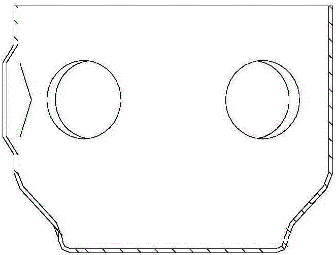
[0038] Such as Figure 1~15 As shown, a 0Cr17Ni4Cu4Nb material multi-pass pipe forming method, the specific steps are as follows:

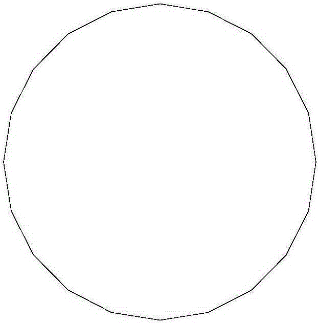
[0039] Step 1: Use a round plate as the original blank, the structure of the original blank is as follows figure 1 Shown

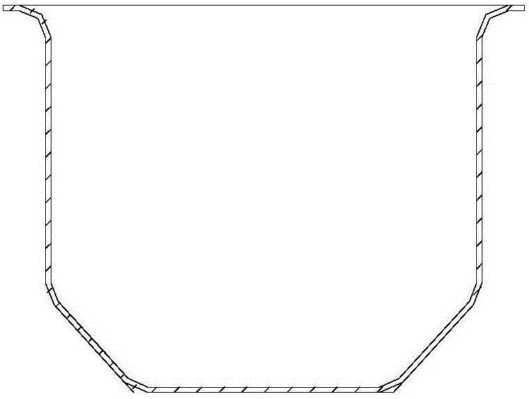
[0040] Step 2: Preparation of the cylindrical blank: the original blank is prepared into a stepped cylindrical blank with multiple drawing processes, and a flange is formed at the opening of the cylindrical blank. The structure of the cylindrical blank is as follows figure 2 Shown

[0041] Step 3: Remove the flange of the cylindrical blank. In order to ensure that the cylindrical blank flanging can be realized and meet the design requirements, the bottom and side walls of the cylindrical blank are pre-expanded by a soft male mold before flanging. The purpose is to supplement the flow of the main body mate...


PUM


Abstract

The invention belongs to the technical field of 0Cr17Ni4Cu4Nb material forming, and particularly relates to a 0Cr17Ni4Cu4Nb multi-way pipe forming method and a sidewall flanging die employed by the same. The problem that such a part cannot be integrally formed, and is required to be welded after being separately formed is solved; the fatigue resistance of the part is greatly improved. The method specifically comprises the following steps of adopting a plate as an original blank; machining the original blank into a barrel-shaped blank; pre-bulging the bottom and the sidewall of the barrel-shaped blank; forming holes in the bottom of the barrel-shaped blank, and forming holes in the middle part of the sidewall of the barrel-shaped blank; flanging the bottom of the blank; flanging the sidewall of the blank by adopting the sidewall flanging die; removing allowance. The sidewall flanging die comprises a die core, a male die set, a female die, a positioning sleeve, a guide sleeve, an outer sleeve and a lower template.

Description

Technical field [0001] The invention belongs to the technical field of 0Cr17Ni4Cu4Nb material forming, and particularly relates to a method for forming a 0Cr17Ni4Cu4Nb material multi-pass pipe fitting and an adopted side wall flanging mold. Background technique [0002] The 0Cr17Ni4Cu4Nb material is a stainless steel material with poor plasticity at room temperature. It is difficult to form. The multi-pass pipe is a stepped cylindrical piece with a complex structure. The diameter of the large end is less than 100mm, and the side wall has a diameter of 20-30mm. Because the elongation of 0Cr17Ni4Cu4Nb material is only about 10% at room temperature, it is very difficult to form multi-pass pipe fittings using 0Cr17Ni4Cu4Nb material. The prior art generally adopts the method of welding after split forming, which has large deformation after welding, and The edges are not round, which greatly affects the use of subsequent components, and affects the welding quality and use safety. Summ...

Claims


Application Information

Patent Timeline
Patent Type & Authority Patents(China)
IPC IPC(8): B21D37/10B21D45/04B21C37/28B21D35/00
CPCB21C37/286B21D35/002B21D37/10
Inventor 段新民徐志强王立成邵天巍吕义郎
Owner SHENYANG LIMING AERO-ENGINE GROUP CORPORATION
Learn More