Supercharge Your Innovation With Domain-Expert AI Agents!
a material transfer device
What is Al technical title?
Al technical title is built by PatSnap Al team. It summarizes the technical point description of the patent document.
A material shifting and driving device technology, applied in the field of mechanical equipment, can solve problems such as economic loss, material scattering, and high labor intensity, and achieve the effect of reducing use restrictions
Active Publication Date: 2016-05-11
WUHU JINGFENG GARDEN MACHINERY TECH
View PDF10 Cites 0 Cited by
Summary
Abstract
Description
Claims
Application Information
AI Technical Summary
This helps you quickly interpret patents by identifying the three key elements:
Problems solved by technology
Method used
Benefits of technology
Problems solved by technology
Material transfer by manpower has the following defects: 1. The labor intensity of workers is high, the material transfer time is long, the efficiency is low, and safety accidents are prone to occur; loss
Method used
Image
Click on the blue label to locate the original text in one second.
Reading with bidirectional positioning of images and text.
Examples
Embodiment Construction
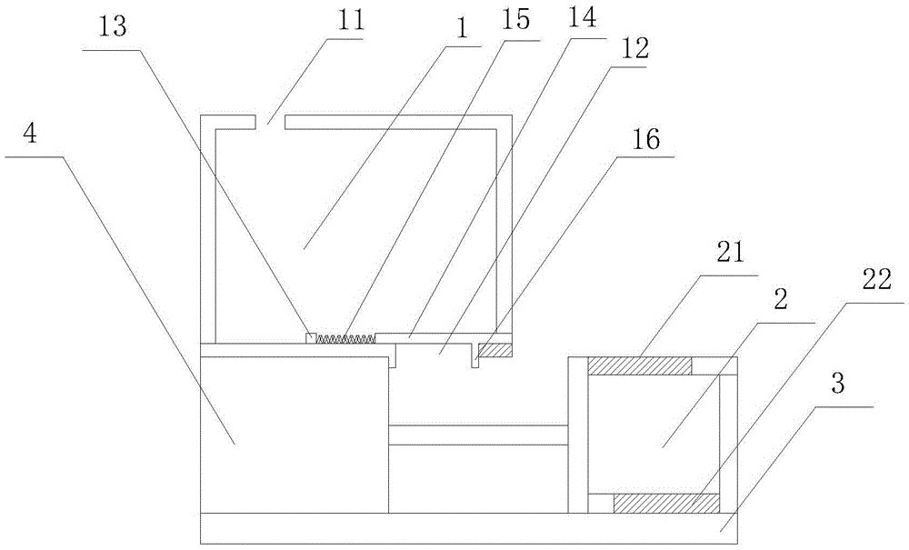
[0011] Such as figure 1 as shown, figure 1 It is a structural schematic diagram of a material transfer device proposed by the present invention.
[0012] refer to figure 1 , in one embodiment, a kind of material shifting device that the present invention proposes, comprises material storage box 1, moving box 2, carrying plate 3 and driving device 4, and carrying plate 3 and moving box 2 are all positioned at storage box 1 below , the moving box 2 is movably installed on the carrying plate 3, the driving device 4 is located on one side of the moving box 2, the driving device 4 is drivingly connected with the side wall of the moving box 2 and drives the moving box 2 to move on the carrying plate 3, the storage box 1 There is a first material inlet 11 at the top of the storage box 1, a first material outlet 12 and a positioning column 13 at the bottom of the material storage box 1, a baffle 14 is provided at the first material outlet 12, and the area of the baffle 14 is large...
PUM
Abstract
The invention discloses a material transferring device, which comprises a material storing box, a moving box, a carrying plate and a driving device, wherein the carrying plate and the moving box are respectively positioned under the material storing box, the moving box is movably arranged on the carrying plate, the driving device is positioned at one side of the moving box, the driving device is in driving connection with the side wall of the moving box and drives the moving box to move on the carrying plate, the top of the material storing box is provided with a first feeding opening, the bottom of the material storing box is provided with a first discharging opening and a positioning post, a baffle plate is arranged at the first discharging opening part, the area of the baffle plate is greater than that of the first discharging opening, one end of the baffle plate is connected with the positioning post through a spring, in addition, the other end of the baffle plate is provided with a pushing rod, one end, far away from the carrying plate, of the pushing rod is fixed with the baffle plate and is abutted against one side, far away from the spring, of the first discharging opening under the effect of the elasticity of the spring, the top of the moving box is provided with a second discharging opening, and one end, far away from the driving device, of the lower part of the moving box is provided with a second discharging opening. The material transferring device disclosed by the invention has the advantages that the semi-automation of the material transferring operation is realized, the transferring efficiency is high, and the operation intensity is low.
Description
technical field [0001] The invention relates to the technical field of mechanical equipment, in particular to a material transfer device. Background technique [0002] At present, when materials are transferred on the workshop site, the materials are usually moved from one space container to another space container by manpower. Material transfer by manpower has the following defects: 1. The labor intensity of workers is high, the material transfer time is long, the efficiency is low, and safety accidents are prone to occur; loss. Therefore, it is necessary to improve the existing material transfer operation mode. Contents of the invention [0003] In order to solve the technical problems existing in the background technology, the present invention proposes a material transfer device, which realizes the semi-automation of material transfer operation, and has high transfer efficiency and low operation intensity. [0004] A material shifting device proposed by the present ...
Claims
Application Information
Patent Timeline
Application Date:The date an application was filed.
Publication Date:The date a patent or application was officially published.
First Publication Date:The earliest publication date of a patent with the same application number.
Issue Date:Publication date of the patent grant document.
PCT Entry Date:The Entry date of PCT National Phase.
Estimated Expiry Date:The statutory expiry date of a patent right according to the Patent Law, and it is the longest term of protection that the patent right can achieve without the termination of the patent right due to other reasons(Term extension factor has been taken into account ).
Invalid Date:Actual expiry date is based on effective date or publication date of legal transaction data of invalid patent.
