
Pipeline boundary layer damping device

A drag reduction device and boundary layer technology, applied in mechanical equipment, fluid flow, etc., can solve the problems of being in the experimental or theoretical research stage, the use of drag reducing agents are limited, and the flexible wall method is difficult to achieve, etc., to achieve drag reduction effect. The effect of obvious, simple structure, convenient and reliable installation

Inactive Publication Date: 2015-02-18
SHENYANG AEROSPACE UNIVERSITY
View PDF6 Cites 10 Cited by
  • Summary
  • Abstract
  • Description
  • Claims
  • Application Information

AI Technical Summary

Problems solved by technology

However, for the scheme design of pipeline drag reduction, the groove method, air bubble method, and soft wall method are not easy to realize; polymer coating drag reduction and wall vibration drag reduction are currently mostly in the experimental or theoretical research stage; although the polymer additive method has been obtained Widely used, but there are too many restrictions on the use of drag reducers, especially not suitable for laminar flow drag reduction

Method used


Image

  • Pipeline boundary layer damping device
  • Pipeline boundary layer damping device
  • Pipeline boundary layer damping device

Examples


Embodiment Construction

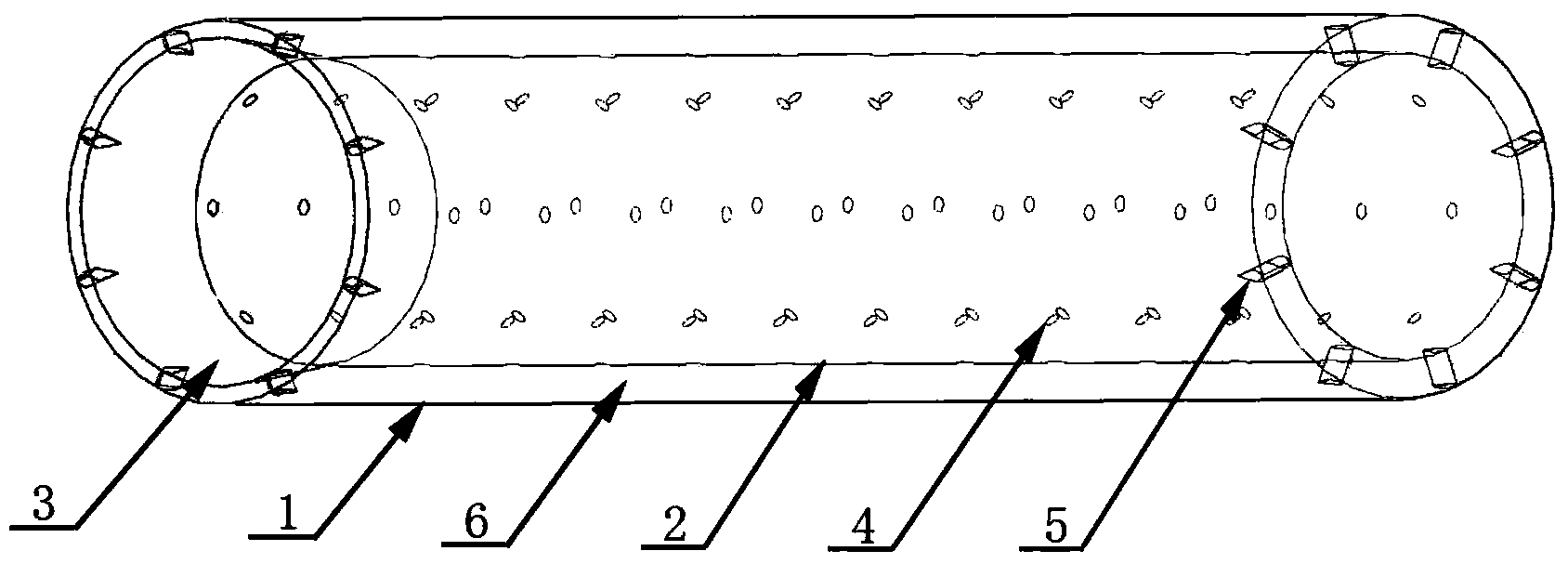
[0015] In order to further understand the drag reducing device for the pipeline boundary layer, the description is as follows with reference to the accompanying drawings.

[0016] It includes an outer tube 1, which is not specially treated, and a thin-walled inner tube 2 is installed inside the outer tube 1, and injection holes 4 are uniformly arranged on the wall of the inner tube 2. The fluid inlet of the inner pipe 1 (the beginning section of the pipeline) is connected with a tapered nozzle 3, the outer diameter of the inner pipe 2 is smaller than the inner diameter of the outer pipe 1, and an interlayer 6 is formed between the inner pipe 2 and the outer pipe 1, and the thickness of the interlayer 6 is determined by the fluid The two ends of the outer tube 1 and the inner tube 2 are respectively connected by a streamlined connecting support plate 5; the connecting support plate 5 is streamlined to reduce the flow resistance entering the interlayer 6; when the fluid flows in,...


PUM


Abstract

The invention relates to a pipeline flow boundary layer damping device, particularly to a boundary layer damping device applied to a conveying pipeline with larger wall viscosity resistance and turbulence intensity. Under the condition that the conventional pipeline is not treated with special processing, a thin wall inner pipe is mounted inside the pipeline, and small holes are formed in the pipe wall of the inner pipe; a gradually shrinking spray pipe is arranged at the fluid inlet of the inner pipe, so that the purpose of forming jetting on the wall surface of the inner pipe is achieved, and the viscosity resistance loss is reduced. For turbulence flow, the boundary layer damping device further has the functions of attenuation of turbulence loss in the pipe diameter direction and rectification. In turbulence flow, when the speed in the pipe diameter direction is higher than the jetting speed, liquid enters an interlayer, when the speed in the pipe diameter direction is not greater than the jetting speed, the jetting effect can be played, so that impact rebound of the fluid on the pipe wall can be reduced, the radial velocity of the mainstream can be quickly offset, and the turbulence is rectified into laminar flow.

Description

technical field [0001] The invention relates to a pipeline flow boundary layer drag reduction device, in particular to a boundary layer drag reduction device applied in a transportation pipeline with relatively strong wall surface viscous resistance and turbulent flow. Background technique [0002] At present, the research and practice of drag reduction methods mainly include groove method, air bubble method, flexible wall method, polymer additive method, polymer coating drag reduction and wall vibration drag reduction, etc. However, for the scheme design of pipeline drag reduction, the groove method, air bubble method, and soft wall method are not easy to realize; polymer coating drag reduction and wall vibration drag reduction are currently mostly in the experimental or theoretical research stage; although the polymer additive method has been obtained Widely used, but there are too many restrictions on the use of drag reducers, especially not suitable for laminar flow drag...

Claims


Application Information

Patent Timeline
Patent Type & Authority Applications(China)
IPC IPC(8): F15D1/06
Inventor 赵国昌单龙宋丽萍
Owner SHENYANG AEROSPACE UNIVERSITY
Learn More