A heat-insulating hanger device for a refrigerant pipe and a method for installing the refrigerant pipe

A technology for refrigerant pipes and hangers, which is applied in the direction of protecting pipes, pipe supports, pipes/pipe joints/fittings through heat insulation, which can solve the problems of high material cost, low installation efficiency, and many insulation gaps, etc., and achieve simplified structure, Improve efficiency and prevent cold bridge effect

Inactive Publication Date: 2016-05-11
CHENGDU IND EQUIP INSTALLATION
View PDF6 Cites 0 Cited by
  • Summary
  • Abstract
  • Description
  • Claims
  • Application Information

AI Technical Summary

Problems solved by technology

[0006] The object of the present invention is to provide a heat-insulating hanger device for refrigerant pipes and a method for installing refrigerant pipes, which mainly solves the problems of many insulation gaps, high material costs, heavy pollution and low installation efficiency in the existing hanger mechanism of refrigerant pipes. question

Method used


Image

  • A heat-insulating hanger device for a refrigerant pipe and a method for installing the refrigerant pipe
  • A heat-insulating hanger device for a refrigerant pipe and a method for installing the refrigerant pipe
  • A heat-insulating hanger device for a refrigerant pipe and a method for installing the refrigerant pipe

Examples


Embodiment

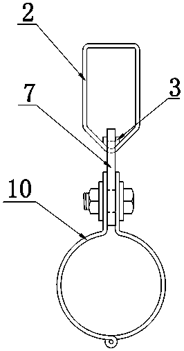
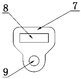
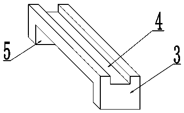
[0040] Such as Figure 1~3 As shown, the present invention is mainly applied to the installation of refrigerant pipes, which includes an elevation adjustment suspension frame 2, a heat insulation saddle 3, a pipe clamp lifting plate 7, and a pipe holding mechanism. Such as figure 2As shown, the pipe clamp lifting plate 7 is respectively provided with a connecting hole 8 and a first threaded hole 9 , wherein the first threaded hole 9 is located below the connecting hole 8 . The connection hole 8 is used for interlocking the elevation adjustment suspension frame 2 and the pipe clamp suspension plate 7 together. The pipe holding mechanism is provided with a second threaded hole and a third threaded hole that are identical in size and shape to the first threaded hole 9, and the pipe holding mechanism is connected by bolts with the first threaded hole and the second threaded hole. Cooperate and connect with pipe clamp hanging plate 7. Specifically, the pipe holding mechanism in...


PUM


Abstract

The invention discloses a heat-insulating hanging bracket device for a refrigerant pipe and a refrigerant pipe installation method thereof. The heat-insulating hanging bracket device comprises an elevation adjustment hanging frame, a pipe clamp hanging plate, a heat-insulating saddle, a first threaded hole and a pipe holding-clamping mechanism, wherein the pipe clamp hanging plate is buckled with the elevation adjustment hanging frame through a connecting hole which is formed in the pipe clamp hanging plate; the heat-insulating saddle is arranged in the connecting hole, and separates the elevation adjustment hanging frame from the pipe clamp hanging plate completely; the first threaded hole is formed in the pipe clamp hanging plate and is positioned below the connecting hole; the pipe holding-clamping mechanism is used for connecting with the refrigerant pipe; the pipe holding-clamping mechanism is provided with a second threaded hole and a third threaded hole; the size and shape of each of the second threaded hole and the third threaded hole are the same with those of the first threaded hole; the pipe holding-clamping mechanism is connected with the pipe clamp hanging plate through the matching between a bolt and each of the first threaded hole, the second threaded hole and the third threaded hole. The heat-insulating hanging bracket device for the refrigerant pipe is reasonable in design, is convenient in assembly and has fewer heat-preservation joint seams; according to the heat-insulating hanging bracket device for the refrigerant pipe, a fireproof heat-insulating pipe carrier with very high cost is eliminated, products can be produced in an industrialized manner, the refrigerant pipe can be fast installed, and the installation elevation can be flexibly adjusted; therefore, the heat-insulating hanging bracket device for the refrigerant pipe is suitable for popularization and application.

Description

technical field [0001] The invention relates to a hanger mechanism, in particular to a heat-insulating hanger device for a refrigerant pipe and a method for installing the refrigerant pipe. Background technique [0002] Most of the hanger mechanisms of the existing refrigerant pipes first use the heat-insulating pipe support to fix the refrigerant pipe, and then use the hanger to lift the refrigerant pipe to the corresponding position of the building. The heat transfer between the hangers prevents condensation from appearing at the place where the refrigerant pipe is installed. This installation method has the following problems: [0003] (1) Heat insulation pipe support needs to be specially made: due to the large size and specification of the refrigerant pipe, the refrigerant pipe support needs to be selected according to the specification of the refrigerant pipe during construction, so that the refrigerant pipe can be fixed smoothly. In this way, when the construction p...

Claims


Application Information

Patent Timeline
Patent Type & Authority Patents(China)
IPC IPC(8): F16L59/135
CPCF16L3/133F16L59/135
Inventor 刘成
Owner CHENGDU IND EQUIP INSTALLATION
Why Eureka
Try Eureka