
Medical electrode for preventing the passage of harmful current to a patient

a technology of harmful electric current and medical electrodes, which is applied in the field of medical electrodes, can solve the problems of needle vaporization, death by electrocution, and damage to the patient's ankle, and achieve the effect of preventing harmful levels of current passing and preventing harmful electric current passing to the patien

Inactive Publication Date: 2005-05-10
RUSSELL MICHAEL J
View PDF24 Cites 95 Cited by
  • Summary
  • Abstract
  • Description
  • Claims
  • Application Information

AI Technical Summary

Benefits of technology

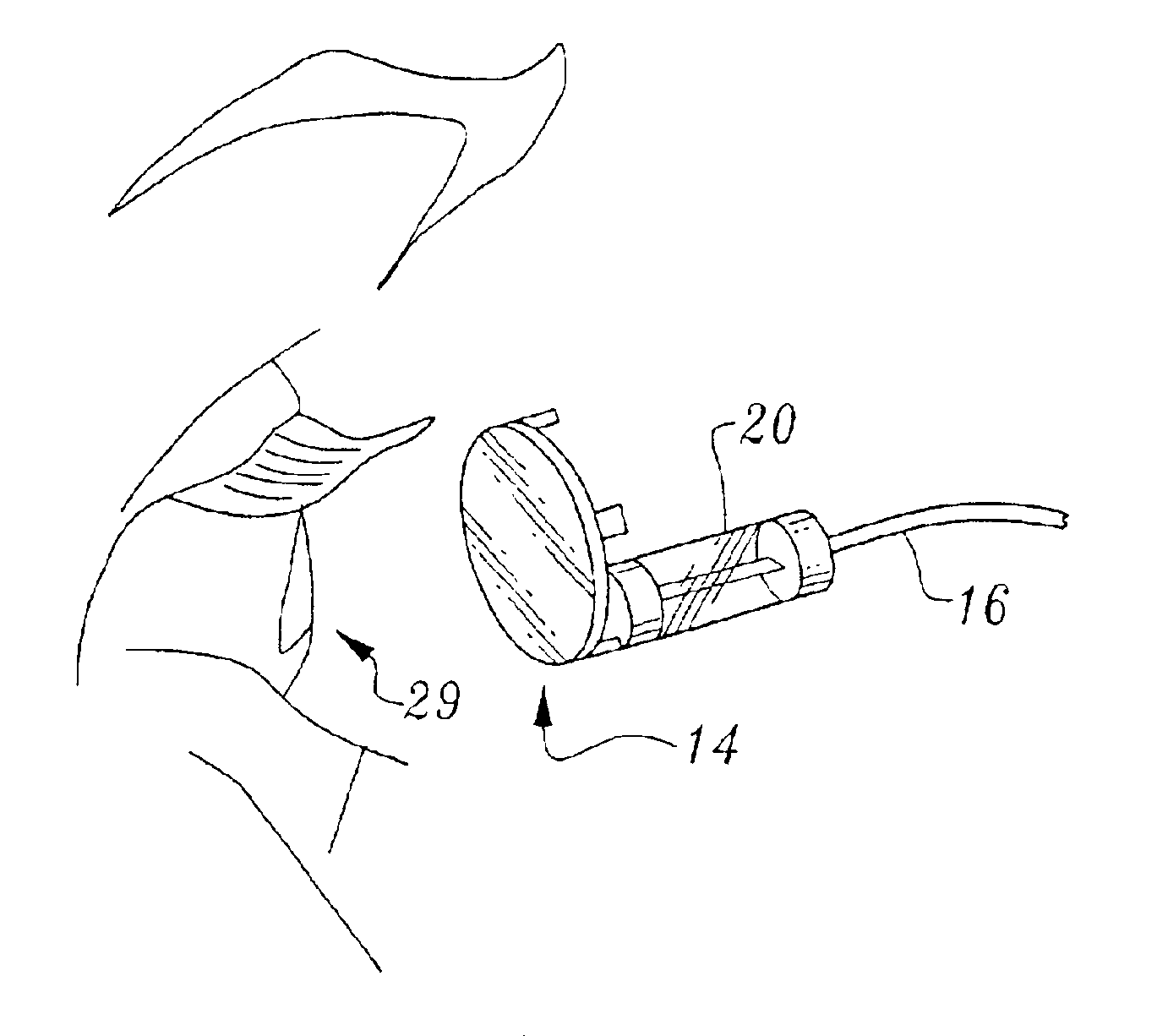
[0024]The present invention is a medical electrode having a current stoppage means for preventing harmful electric current from passing to a patient. This stoppage means may be located at any point upon the electrode for purposes of preventing harmful levels of current passing from an AC power source to a patient. However, for additionally preventing induction current from passing to a patient, the preferred location of the current stoppage means is on the proximal end of the electrode, aft of the wire lead element of the electrode.
[0026]Accordingly, the following objects and advantages of the invention apply:
[0028]It is an object of this invention to provide a medical electrode that can prevent the passage of harmful current to a patient.
[0029]It is another object of this invention to provide a medical electrode that is inexpensive to manufacture.
[0030]It is another object of this invention to provide a medical electrode that can prevent the passage of harmful current to a patient, wherein the harmful current originates from either an AC power source or an inductance current source.

Problems solved by technology

However, it has been documented in a number of cases that the passage of current through a medical electrode connected to a patient has resulted in tissue burns, and even death by electrocution.
It was found that enough heat had been generated such that the needles had vaporized and left a hole in the patient's ankle.
A technician had encountered a minor problem with an electrode burn on a patient, which had occurred during feedback to an electro-cautery machine being used in an operating room, while performing a neuromonitoring procedure.
The coiled wires acted as an induction coil receiver and further amplified the signal causing a significant bum on the patient.
A neuromonitoring technician placed skin surface electrodes on a patient, but did not insure that the grounding impedances were low.
The electro-cautery being used in the surgery was faulty, and the neuromonitoring equipment allowed current to pass from the patient to the ground leads and caused bums upon the patient.
However, to date, the major focus with regard to medical electrode safety measures has been to deal with the electrocution problem, because this is the problem that can have the gravest consequences.
These adaptors typically bear warning indicia such as “Warning: Do Not Use With AC Power Source or Apnea Monitors.” However, these adaptors still convert the female connector end back to a male end, which despite such warnings, still present a real possibility of causing electrocution from plugging into a wall outlet.
Moreover, while the addition of adaptors present a better solution to the problem of electrocution from wall sockets, adaptors do not solve the problem of tissue bums and electrocution due to induction current phenomena.
So far, the answer to this inductance problem has been to post warnings on electrode packaging of the type shown on the packaging produced by Astro-Med, Inc., Grass Instrument Division of West Warwick, R.I. While package warnings certainly help keep medical personnel alert to the inductance problem, mere warnings are insufficient to stop tissue all tissue burns and electrocutions from occurring.
Many of the case histories noted previously involved electrical devices that had some type of built-in current stoppage means, yet harmful current was still passed to the electrodes to injure patients.
Therefore, past solutions, have been inadequate to prevent the problem of bums and electrocution from harmful current passage through electrodes.
These standards clearly show that as of yet, medical electrode design has not provided any closure to this burning problem.

Method used


Image

  • Medical electrode for preventing the passage of harmful current to a patient
  • Medical electrode for preventing the passage of harmful current to a patient
  • Medical electrode for preventing the passage of harmful current to a patient

Examples


Embodiment Construction

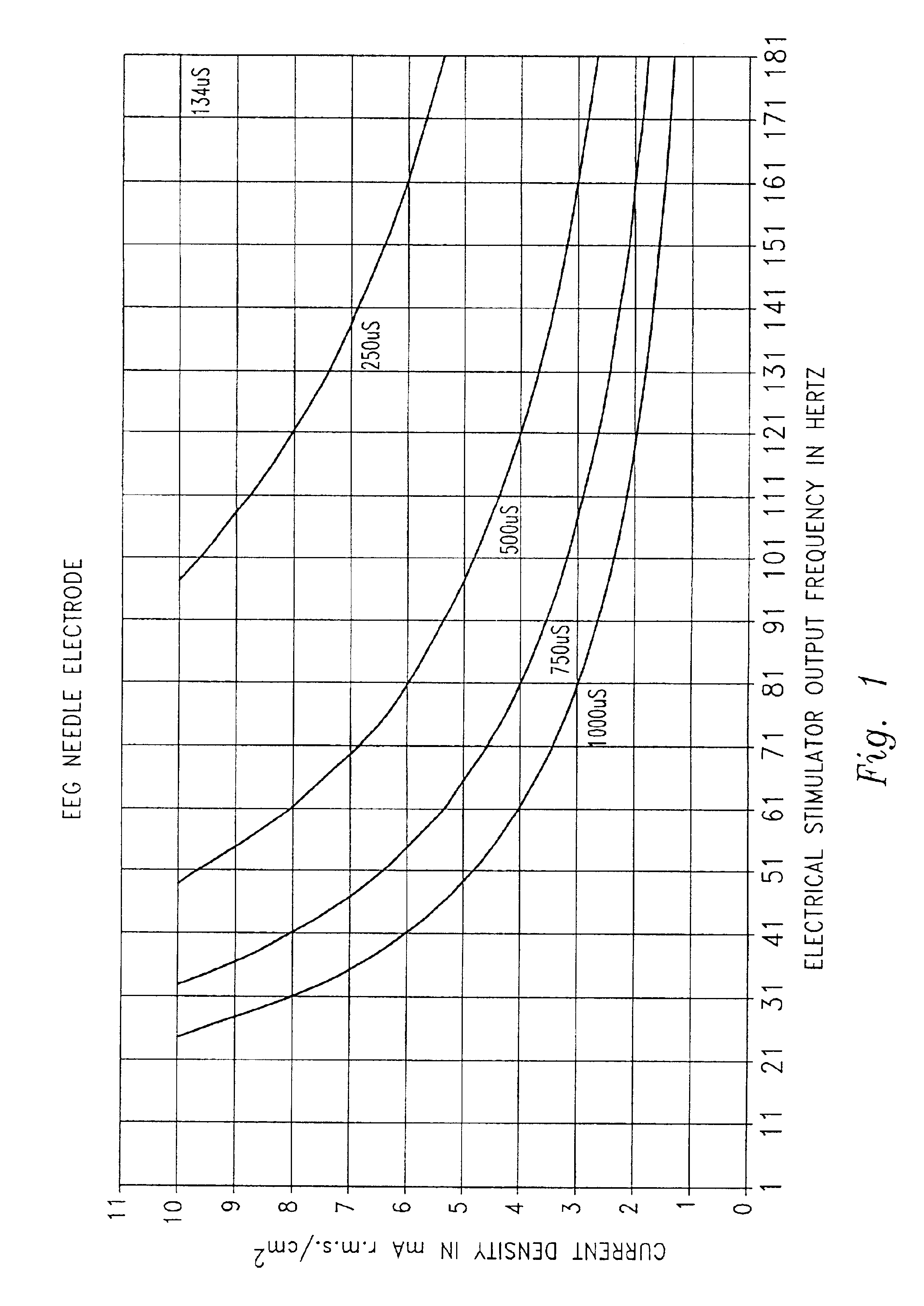
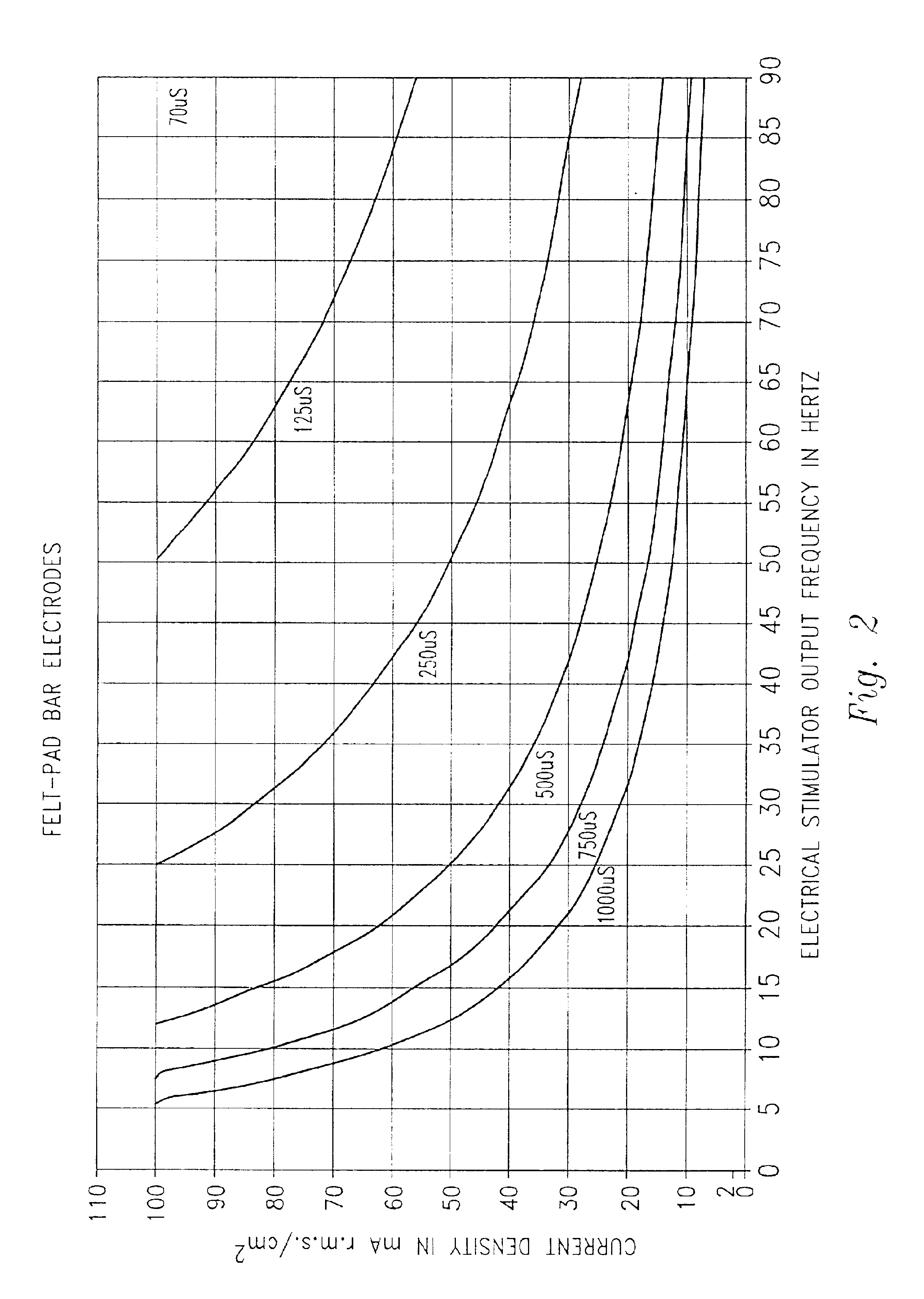
[0049]The inventive medical electrode described herein stops the passage of harmful current to a patient. “Harmful current” as it is used here translates to current densities that are capable of causing tissue burns or even death by electrocution. Current density corresponds to the amount of current being applied to a square centimeter of tissue surface area. The International Electrotechnical Commission (IEC standard 60601-2-40) has established a current density of 2 mA r.m.s. / cm2 as a safety limit. Current densities beyond this safety limit tend to cause burns or electrocution.

[0050]FIGS. 1 and 2 illustrate graphs showing the relationship of the variables of electrode surface area, time of applied current, and current frequency (in Hertz) on current density(mA r.m.s. / cm2). FIG. 1, is illustrative of a needle electrode, which has a small surface area, and FIG. 2 is for a felt-pad bar electrode having a large surface area. Each curve on the graphs is representative of current densit...


PUM


Abstract

A medical electrode designed to prevent the passage of harmful electric current to a patient, thereby preventing tissue damage and electrocution. In the preferred embodiment, the inventive medical electrode is comprised of a proximal end, a distal end, a conductive lead connecting the proximal and distal ends, and a fuse located upon the medical electrode for preventing the passage of harmful electric current to a patient. For additional protection from induction current, the preferred location of the fuse is aft of the conductive lead element of the electrode. While a fuse is used in the preferred embodiment, the fuse could be replaced with a diode or a circuit breaker.

Description

CROSS REFERENCE TO RELATED APPLICATIONS[0001]This is a continuation-in-part of U.S. patent application Ser. No. 09 / 903,778 filed on Jul. 11, 2001 abandoned.TECHNICAL FIELD[0002]This invention relates to medical electrodes, and more particularly, to preventing the passage of harmful electric current through a medical electrode attached to a patient.BACKGROUND[0003]Medical electrodes have been used for years to accomplish various clinical functions, including nerve stimulation, bio-feedback monitoring, electromyographs, and electroencephalograph (EEG) tests, to name a few. Medical electrodes are designed to either send electric current, from an electrical medical device to a living being, or else receive electric current generated by a living being. Medical electrodes can be used in both a human patient environment and in a veterinary environment.[0004]Medical electrodes are generally comprised of a proximal end for coupling to a patient, a distal end for connecting to a medical appli...

Claims


Application Information

Patent Timeline
Patent Type & Authority Patents(United States)
IPC IPC(8): A61B5/0402A61B5/0428A61B5/0488A61B5/0492A61B5/0476A61B5/0478A61B5/296A61B5/308
CPCA61B5/04282A61B5/0492A61B5/0478A61B5/301A61B5/291A61B5/296
Inventor RUSSELL, MICHAEL J.
Owner RUSSELL MICHAEL J
Learn More