Osmotic membrane and vacuum system for artificial limb

a vacuum system and artificial limb technology, applied in the field of prosthetic devices, can solve the problems of not revealing the application of vacuum to the socket cavity, irritation of the residual limb, and the wearer's feeling of losing contact with the artificial limb, so as to reduce the pressure in the socket cavity, the effect of reducing the pressur

Inactive Publication Date: 2005-12-13
SANYO ELECTRIC CO LTD
View PDF116 Cites 106 Cited by
  • Summary
  • Abstract
  • Description
  • Claims
  • Application Information

AI Technical Summary

Benefits of technology

[0012]A system for removing perspiration from a residual limb inserted in a prosthesis comprising an nonporous prosthesis socket, a porous thin sheath adjacent the socket, a nonporous liner adjacent the sheath, an osmotic membrane adjacent the liner allowing water vapor to pass from the limb but preventing liquid from passing to the limb, a nonporous seal that prevents air leakage between the residual limb and the socket; and a vacuum source to reduce the pressure in a space between the limb and socket.
[0013]A method of removing perspiration from a residual limb in a prosthesis comprising the steps of inserting the residual limb into a sleeve comprising an osmotic membrane that allows water vapor to pass from the limb but prevents liquid from passing to the limb. The residual limb and osmotic membrane sleeve are inserted into a flexible, nonporous liner. The residual limb, osmotic membrane sleeve, and liner are inserted into a porous sheath. The residual limb, osmotic membrane sleeve, liner, and sheath are inserted into a prosthetic socket cavity having a volume and shape to receive the residual limb. The socket cavity is sealed with a nonporous seal, and vacuum applied to the socket cavity in the space between the membrane and the socket to draw the residual limb and liner into firm contact with the socket and provide a reduced pressure in the socket cavity.

Problems solved by technology

As this perspiration buildup continues, the residual limb begins to slip around within the liner, causing a feeling to the wearer of losing contact with the artificial limb.
This slippage often also causes irritation to the residual limb, which may be worsened by a growth of bacteria in the warm, moist environment between the residual limb and the liner.
In any case, the patent does not disclose application of vacuum to the socket cavity in such a manner as to draw the residual limb firmly and totally against the interior of the socket.
Also, the patent does not disclose the use of vacuum to remove perspiration.
Also, this patent does not disclose a mechanism for maintaining vacuum in the presence of air leakage into the socket.
It has been found that it is essentially impossible to maintain a perfect, airtight seal between the residual limb and the sockets disclosed in U.S. Pat. No. 5,549,709, with the result that slow air leakage into the sockets diminishes the vacuum in the sockets.

Method used


Image

  • Osmotic membrane and vacuum system for artificial limb
  • Osmotic membrane and vacuum system for artificial limb
  • Osmotic membrane and vacuum system for artificial limb

Examples


Embodiment Construction

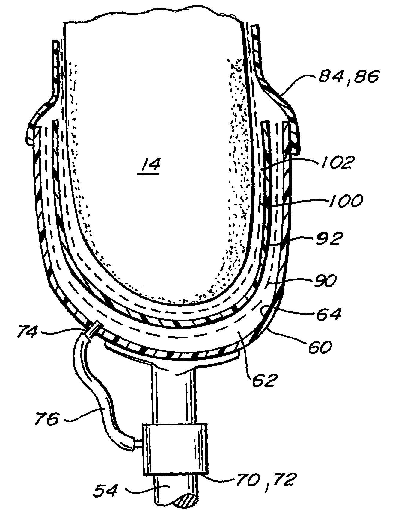
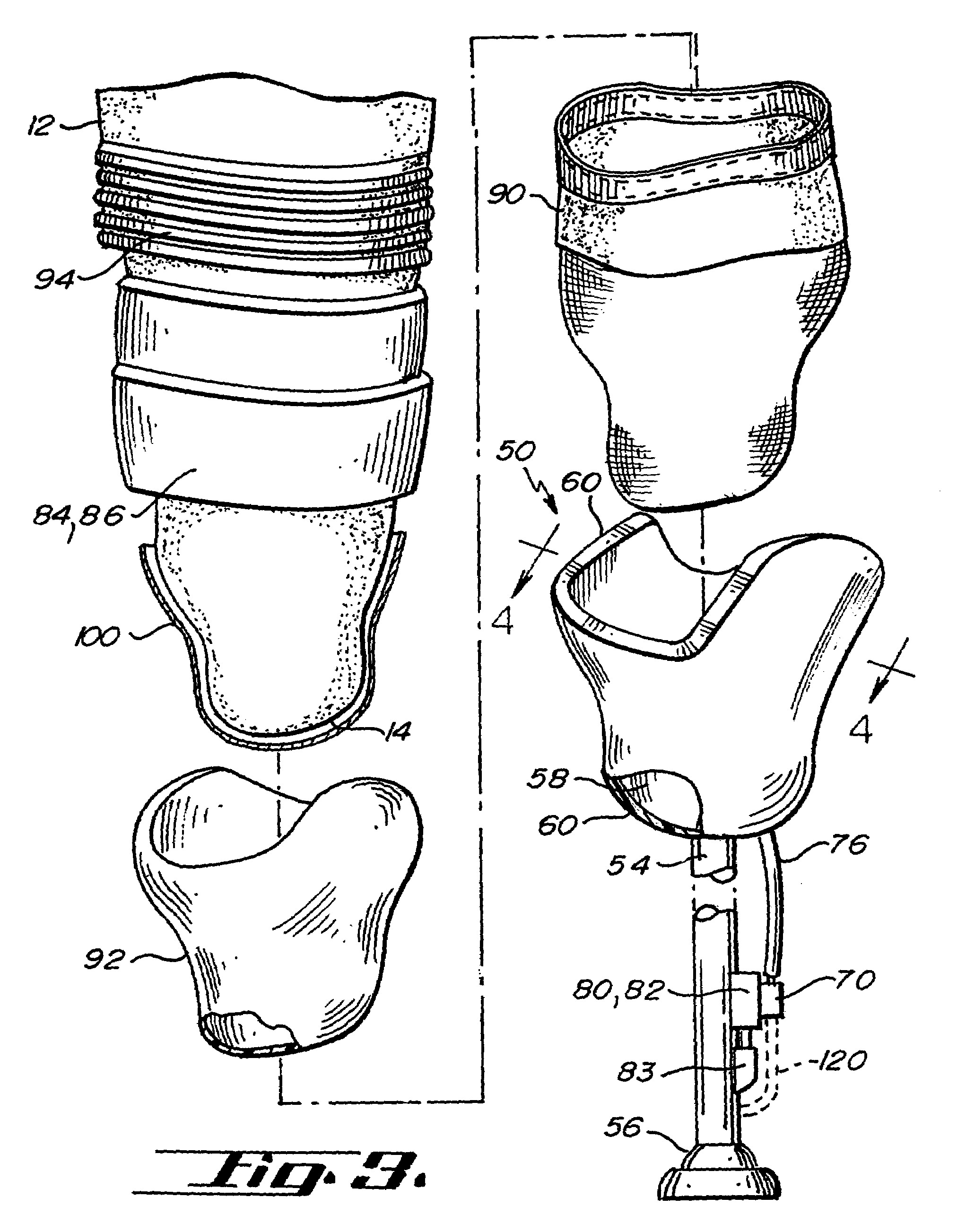
[0018]FIGS. 3 and 4 show one embodiment of the apparatus 50 of the present invention. The hypobarically-controlled artificial limb 50 includes a single socket 60, shin 54, and foot 56. The socket 60 has a volume and shape to receive a substantial portion of the residual limb 14 with a space 58 therebetween.

[0019]The apparatus 50 further includes a cavity 62 in the socket 60 with a volume and shape for receiving a substantial portion of the residual limb 14.

[0020]A vacuum source 70 may conveniently be attached to the shin or pylon 54. The vacuum source 70 may preferably be a mechanical or motor-driven pump 72. The vacuum source 70 may be connected to a power source 83, which may be a battery.

[0021]A vacuum valve 74 is suitably connected to the vacuum source 70. The vacuum valve 74 may preferably be disposed on the socket 60. A vacuum tube 76 connects the vacuum valve 74 to the cavity 62. It will be seen that the vacuum source will cause the residual limb 14 to be drawn into firm cont...


PUM


Abstract

A system for removing perspiration from a residual limb inserted in a prosthesis comprising an nonporous prosthesis socket, a porous thin sheath adjacent the socket, a nonporous liner adjacent the sheath, an osmotic membrane adjacent the liner allowing water vapor to pass from the limb but preventing liquid from passing to the limb, a nonporous seal that prevents air leakage between the residual limb and the socket; and, a vacuum source to reduce the pressure in a space between the limb and socket. A method of removing perspiration from a residual limb in a prosthesis.

Description

CROSS-REFERENCE TO RELATED APPLICATION[0001]This is a continuation of U.S. patent application Ser. No. 09 / 829,306, filed on Apr. 9, 2001, now abandoned which is a continuation-in-part of U.S. patent application Ser. No. 09 / 325,297, filed Jun. 3, 1999, now abandoned, and U.S. patent application Ser. No. 09 / 534,274, filed Mar. 23, 2000, issued as U.S. Pat. No. 6,554,868.BACKGROUND OF THE INVENTION[0002]The present invention relates to prosthetic devices and more particularly to a hypobarically-controlled artificial limb for amputees and to a method for removing perspiration from the space between the residual limb and the liner by means of an osmotic membrane and an applied vacuum.[0003]An amputee is a person who has lost part of an extremity or limb such as a leg or arm which commonly may be termed as a residual limb. Residual limbs come in various sizes and shapes with respect to the stump. That is, most new amputations are either slightly bulbous or cylindrical in shape while older...

Claims


Application Information

Patent Timeline
Patent Type & Authority Patents(United States)
IPC IPC(8): A61F2/00A61F2/50A61F2/60A61F2/66A61F2/70A61F2/74A61F2/76A61F2/78A61F2/80A61F13/15
CPCA61F2/5046A61F2/7812A61F2/7843A61F2/80A61F2/5044A61F2/601A61F2002/5003A61F2002/5015A61F2002/5052A61F2002/5053A61F2002/6614A61F2002/704A61F2002/747A61F2002/7655A61F2002/7818A61F2002/802A61F2013/15528A61F2210/0057A61F2/74
Inventor CASPERS, CARL A.
Owner SANYO ELECTRIC CO LTD
Why Eureka
Try Eureka