Thermal Cycler for Microfluidic Array Assays

a microfluidic array and cycler technology, applied in the field of devices and methods for assaying samples, can solve the problems that the pcr to achieve higher throughputs with conventional technology is neither cost effective nor efficient, and achieve the effect of preventing fogging and promoting sample spread

Inactive Publication Date: 2011-01-06
LIFE TECH CORP
View PDF107 Cites 97 Cited by
  • Summary
  • Abstract
  • Description
  • Claims
  • Application Information

AI Technical Summary

Benefits of technology

[0018]In further related embodiments to the invention described herein, a funnel guide may be coupled to the case, the array capable of being inserted into the case by passing the array through the funnel guide and an opening of the case. The funnel guide may be removably attached to the case. The funnel guide may include walls defining a slit, the array capable of being passed through the slit. Liquid may be substantially prevented from passing through the slit in the absence of the array due to, for example, surface energy. The walls defining the slit may be capable of being deformed to allow the array to pass through the slit, and may be made, for example, of plastic. The slit may be capable of being opened and closed. The funnel guide may include brushes for spreading of the at least one of sample and reagent. The at least one cover of which is light transmissive may be coated with a hydrophilic layer to prevent fogging. At least one of the frame and the covers may includes a hydrophilic strip for promoting spreading of sample during array loading. At least one of the array and the case may include an identifier, such as a barcode.
[0032]In accordance with another embodiment of the invention, a method of conducting an assay on a plurality of samples includes performing an assay at each sample site in a sample array having greater than 100 sample sites. Each assay provides an optical effect. Each of the sample sites simultaneously imaged to produce imaging data pertinent to the optical effect of each site.
[0034]In accordance with another embodiment of the invention, a method of conducting an assay on a plurality of samples includes performing an assay at each of a plurality of sample sites in a sample array, the sample array having a sample site density greater than one sample site per 20 mm2. Each assay provides an optical effect. Each of the sample sites is simultaneously imaged to produce imaging data pertinent to the optical effect of each site.
[0036]In accordance with another embodiment of the invention, a method of conducting an assay on a plurality of samples includes performing an assay at each of a plurality of sample sites in a sample array. Each assay provides an optical effect. Each sample site is simultaneously illuminated using one or more colored LEDs. Furthermore, each of the sample sites is simultaneously imaged to produce imaging data pertinent to the optical effect of each site.
[0043]In further related embodiments, the thermal cycler may include a deck, which may be a smooth surface, for placing the microfluidic array prior to loading or removal from the thermal block. The deck may include an edge onto which the microfluidic array can be placed, whereupon the microfluidic array can be rotated onto the thermally controlled surface of the flat block. The thermal cycler may include a finger element for pressing the microfluidic array against the thermal block. The finger element aids in improving thermal contact between the case and flat block and preventing the case from moving relative to the illuminated and imaged area during temperature cycling. The finger element may be flexible. The finger element may be coated with an insulating material. The thermal cycler may include a lid assembly. The lid assembly may include the finger element. The fingers may touch the microfluidic array before the lid assembly is closed, such that a force is applied to the microfluidic array when the lid assembly is closed. The finger element may not be part of the lid assembly and may be placed on the case prior to closing the lid. The finger element may contact the case at one or more points.
[0050]In related embodiments of the invention, the array may include a hydrophobic surface surrounding the openings of each sample site. The sample sites may include a hydrophilic surface that attracts the at least one of sample and reagent. The sheet may have a pair of opposed surfaces and a thickness, and the sample sites include a plurality of through-holes running through the thickness between the surfaces. The sample sites may include a plurality of closed-ended wells. At least one cover of which is light transmissive may be coated with a hydrophobic layer to prevent fogging. The array may include a recessed opening at each sample site, the recess preventing fluid in each sample site from coming into contact with a cover to which each such sample site is proximate. The system may further include one of a UV curable sealant and a grease for sealing the opening. The frame and the covers may be coupled together to form the case by at least one of an epoxy or other adhesive. The frame may be, or include, an adhesive gasket or a compression gasket. The frame may be puncturable and include includes walls defining a hole, the hole filled with a self-sealing material, which may be, for example, a grease. The system may further include a funnel guide coupled to the case, the array capable of being inserted into the case by passing the array through the funnel guide and the opening. The funnel guide may be removably attached to the case. The funnel guide may includes walls defining a slit, the array capable of being passed through the slit. Liquid may be substantially prevented from passing to through the slit in the absence of the array due to, at least in part, surface energy. The walls defining the slit may be capable of being deformed to allow the array to pass through the slit, The funnel guide may include brushes for spreading of the at least one of sample and reagent. At least one of the frame and the covers may include a hydrophilic strip for promoting spreading of sample during array loading.

Problems solved by technology

Despite this apparent success, it is well-established microarray data is fraught with errors from a variety of sources with the greatest contribution from the platform itself.
PCR is a solution-phase assay carried out in 96- or 384-well microplates and scaling PCR to achieve higher throughputs with conventional technology is neither cost effective nor efficient.
A critical challenge in reaching this level of performance is the physical isolation of the reaction volumes to prevent evaporation and fluidic cross-talk between adjacent containers during thermal cycling and loading of sample and primers.

Method used


Image

  • Thermal Cycler for Microfluidic Array Assays
  • Thermal Cycler for Microfluidic Array Assays
  • Thermal Cycler for Microfluidic Array Assays

Examples


Embodiment Construction

[0082]Definitions. As used in this description and the accompanying claims, the following terms shall have the meanings indicated, unless the context otherwise requires:

[0083]“Target” may be any molecule, nucleic acid, protein, virus, cell, or cellular structure of interest.

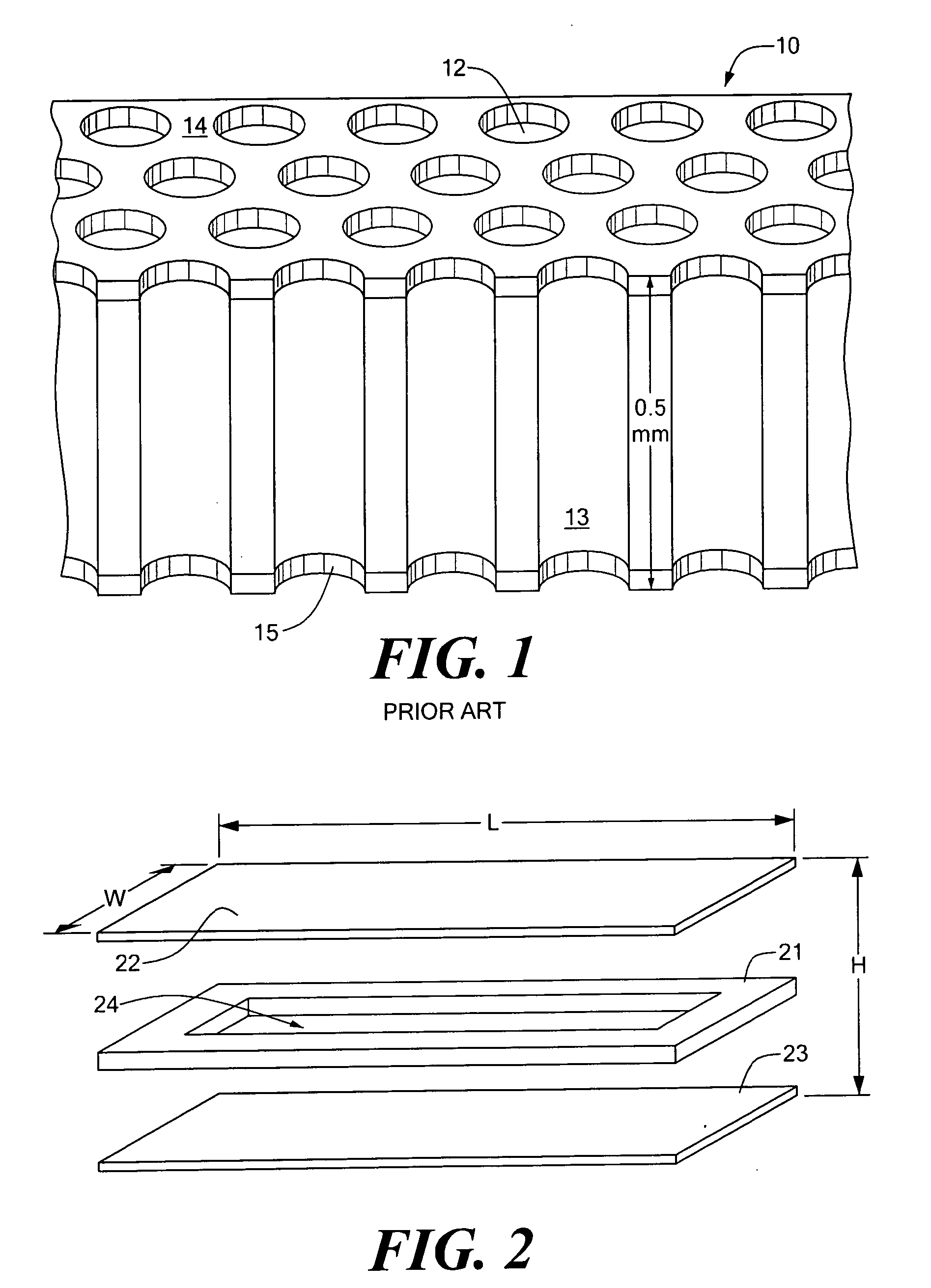
[0084]“Microfluidic array” refers to any ordered structure for holding liquid samples of 1000 nanoliters or less.

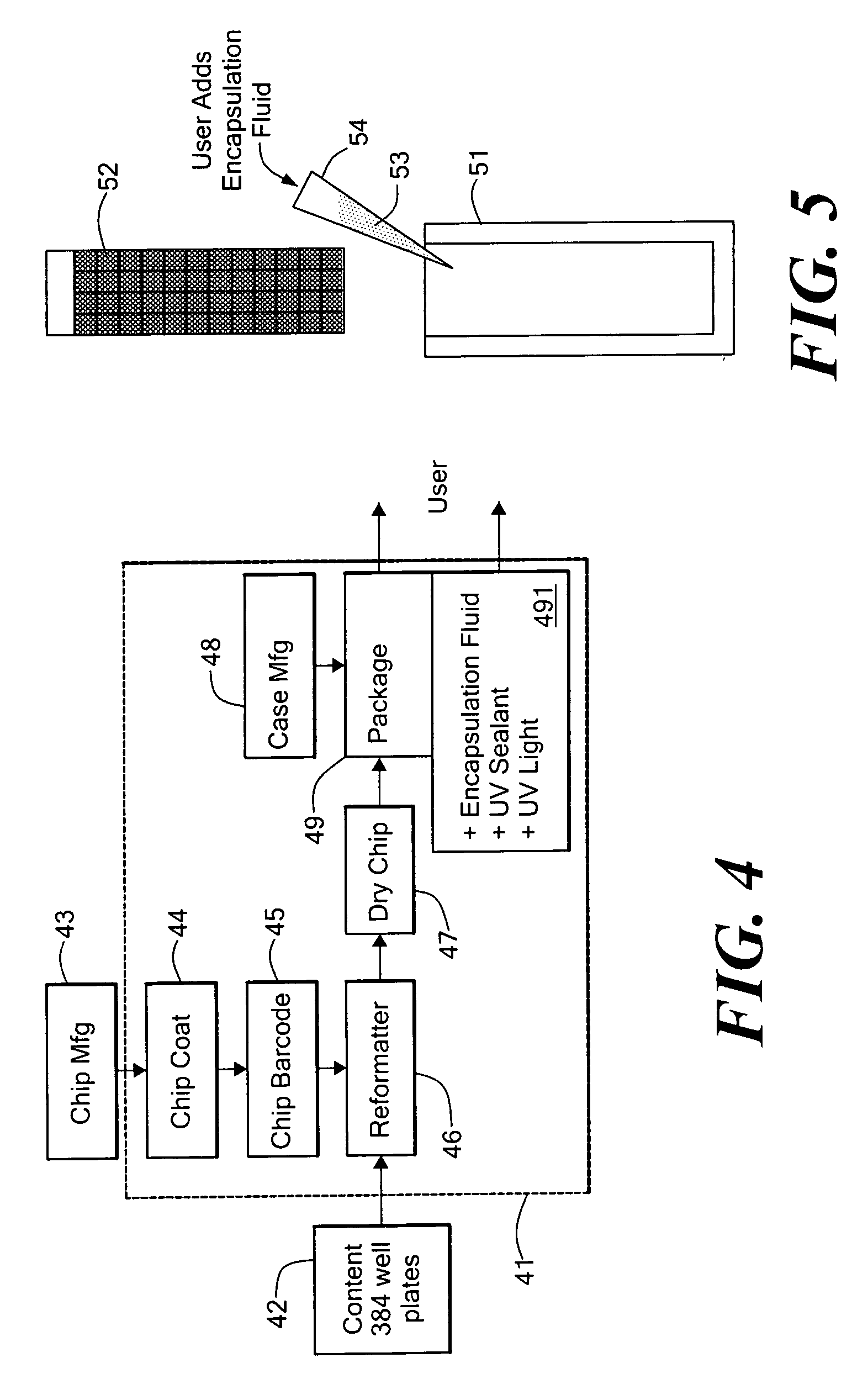
[0085]Embodiments of the present invention are directed to devices and methods for assaying sample liquids using a microfluidic sample array. For example, various techniques for encasing, loading, stacking, thermal cycling and imaging of a microfluidic sample array are presented. Other embodiments of the present invention include adapting individual through-holes of the sample array for capture, chemical processing of captured targets, and / or multi-functional processing of liquid samples. Various examples and embodiments are discussed in detail below.

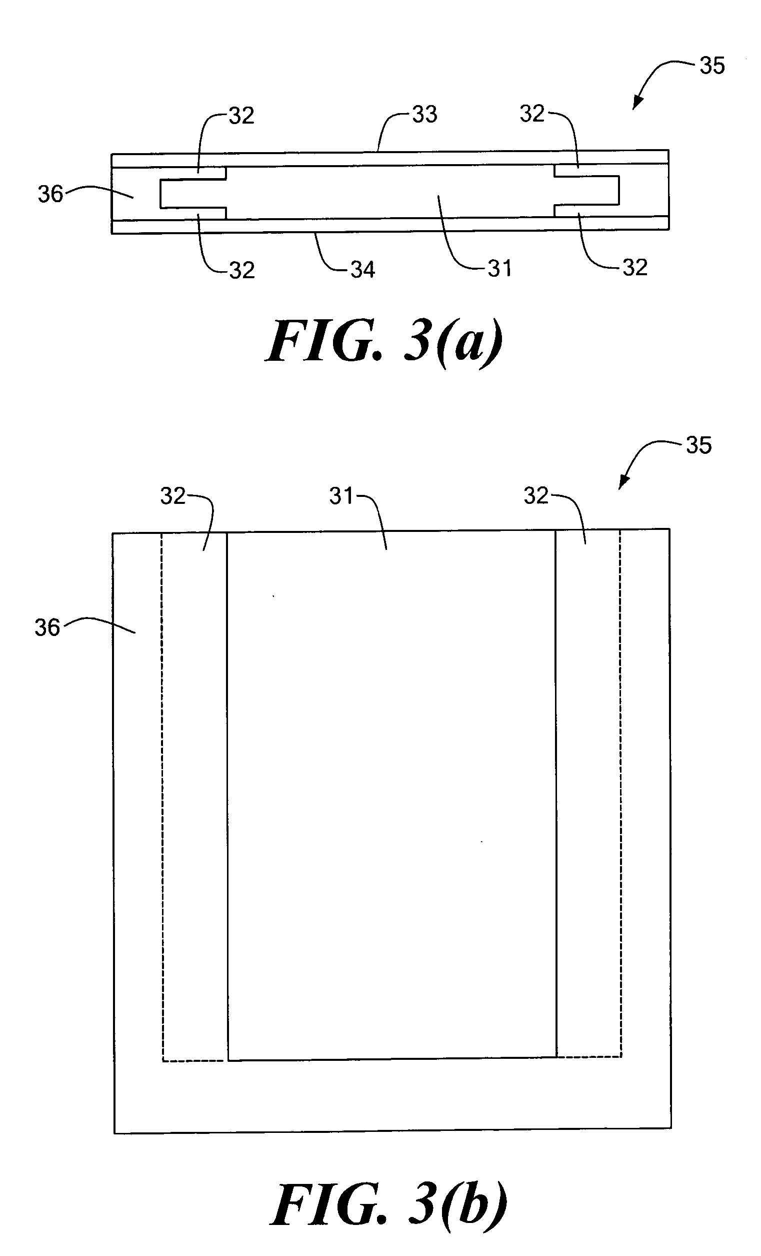
[0086]Encased Microfluidic Array

[0087]FIG. 2 is an e...


PUM

PropertyMeasurementUnit
volumeaaaaaaaaaa
thickaaaaaaaaaa
thickaaaaaaaaaa

Abstract

A system for thermal cycling a plurality of samples. The system includes a case having a fluid-tight cavity defining an interior volume. A microfluidic array is disposed in the interior volume, the array including a sheet of material having a pair of opposed surfaces, a thickness, and a plurality of through-holes running through the thickness between the surfaces. A thermal cycler having at least one thermally controlled surface is adapted to thermally contact the case.

Description

CROSS REFERENCE TO RELATED APPLICATIONS[0001]This application is a continuation of Ser. No. 11 / 227,425, filed Sep. 15, 2005, which claims priority from U.S. Provisional Application Ser. No. 60 / 610,033, filed Sep. 15, 2004, entitled “Thermal Cycler for Microfluidic Array Assays.” This application is also a continuation-in-part of U.S. patent application Ser. No. 10 / 744,580, filed on Dec. 22, 2003, entitled “Assay Apparatus and Method Using Microfluidic Arrays,” which in turn claims priority from U.S. Provisional Application Ser. No. 60 / 434,988, entitled “Chip Temperature Cycling,” filed Dec. 20, 2002; U.S. Provisional Application Ser. No. 60 / 461,559, entitled “Immobilized Probe Nanotiter Array,” filed Apr. 9, 2003; U.S. Provisional Application No. 60 / 528,461, entitled “Improved Selective Ligation and Amplification Assay” filed Dec. 10, 2003; and U.S. Provisional Application Ser. No. 60 / 461,556, entitled “High-Density Microfluidic Thermal Cycling with Stackability,” filed Apr. 9, 2003...

Claims


Application Information

Patent Timeline
Patent Type & Authority Applications(United States)
IPC IPC(8): C40B30/00C40B60/14C40B60/08C40B50/06
CPCB01L3/508B01L3/50857B01L7/02B01L7/52B01L2200/025B01L2200/0684B01L2300/185B01L2300/021B01L2300/0636B01L2300/0819B01L2300/0822B01L2300/1822B01L2300/1838B01L2200/0689
Inventor YODER, KARLBRENAN, COLINLINTON, JOHNHASAN, LEILAELLIS, ROBERTKATZ, ARRINMORRISON, TOMFONSECA, JORGE
Owner LIFE TECH CORP
Why Eureka
Try Eureka