Beam component bending and torsion combined load test device and method

A loading device and combined loading technology, used in measuring devices, using stable bending force to test material strength, instruments, etc., can solve the problem that the bending moment boundary conditions are not ideal simply supported, the beam members are not ideal rotation, and the loading device is difficult to achieve and other problems, to achieve the effect of ingenious and reasonable setting of boundary conditions, intuitive and convenient measurement, and low cost

Active Publication Date: 2015-02-18
INST OF ENGINEERING THERMOPHYSICS - CHINESE ACAD OF SCI
View PDF9 Cites 23 Cited by
  • Summary
  • Abstract
  • Description
  • Claims
  • Application Information

AI Technical Summary

Problems solved by technology

At present, there are few experiments on combined bending and torsion loading of beam members, mainly because the loading device is difficult to realize, for example, the boundary condition of bending moment is not ideally simply supported, and the beam member is not ideally rotated when the torque is applied, so it is difficult to obta

Method used


Image

  • Beam component bending and torsion combined load test device and method
  • Beam component bending and torsion combined load test device and method
  • Beam component bending and torsion combined load test device and method

Examples


Embodiment Construction

[0024] In order to make the object, technical solution and advantages of the present invention clearer, the present invention will be further described in detail below with reference to the accompanying drawings and examples.

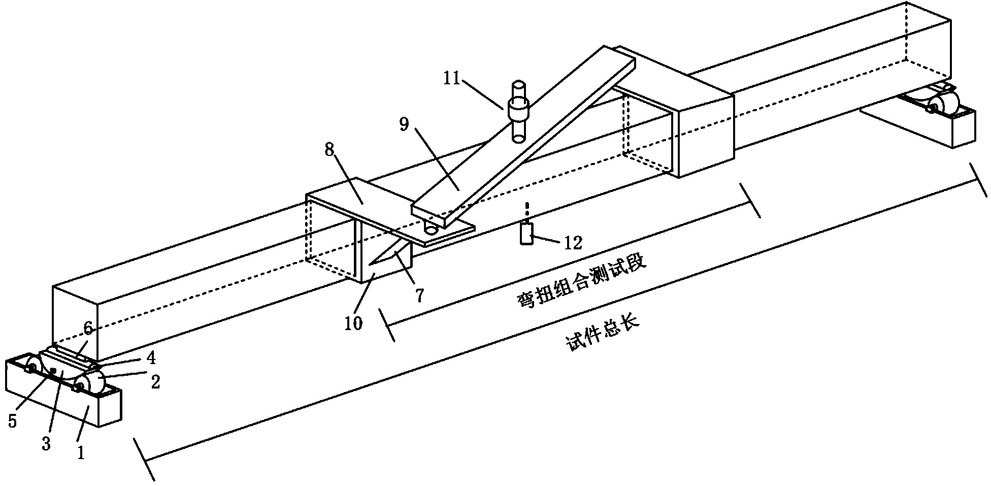
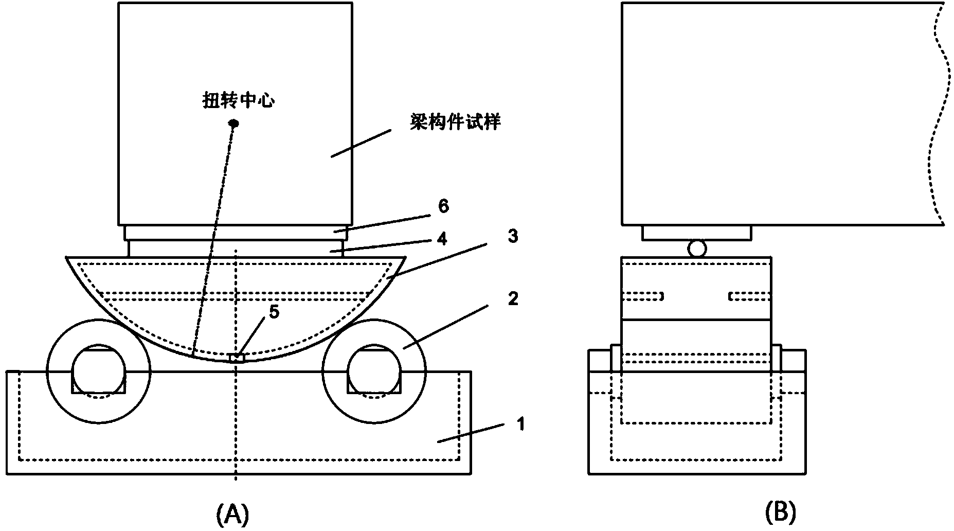
[0025] Such as Figure 1~2 As shown, the beam member bending-torsion combined loading test device of the present invention includes two parts, a simply supported-torsion combined support and a combined loading component. The simply supported-torsion combined support includes a fixed base 1, a roller 2, a torsion support 3, a simply supported support 4, an electronic torsion angle meter 5, and a backing plate 6. A simply supported-torsion combined support is fixed at both ends of the sample to support the sample and control the boundary conditions. Specifically: a number of rollers 2 are placed on the fixed base 1, the rollers 2 support the torsion support 3, and an electronic torsion angle meter 5 is installed. This part of the structural combination i...


PUM


Abstract

The invention relates to a beam component bending and torsion combined load test device and method. The beam component bending and torsion combined load test device comprises simply support and torsion combined supporting seats and combined loading components, wherein the simply support and torsion combined supporting seats are mounted at two ends of a beam component sample, a part with certain length in the middle area of the sample is taken as a testing section, and the combined loading components are arranged at the testing section. Specifically, two horizontally reversed loading arms are mounted at two ends of the testing section respectively, and free ends of the two loading arms are fixedly connected through a distributing beam. During testing, pressure is applied to the middle of the distributing beam, so that the sample is bent; and the distributing beam averagely distributes and transfers the pressure to the free ends of the two loading arms, and accordingly, two ends of the testing section of the sample relatively perform reverse torsion. According to a measured torsion angle, bending deflection and pressure load, a bending moment and deflection curve and a torque and turn angle curve under bending and torsion combined loading of a beam component can be obtained. According to the device and the method, bending and torsion combined loading of the beam component can be realized only by applying one pressure load, boundary conditions are ingeniously and reasonably set, parameter measurement is intuitive and convenient, and testing data are accurate.

Description

technical field [0001] The invention relates to a test loading device, in particular to a beam member bending-torsion combined loading test device and method. Background technique [0002] In engineering, bridges, concrete beams, steel pipes, power transmission towers, wind turbine blades, etc. can all be simplified into beam components. Under complex forces such as wind loads and earthquakes, not only axial forces and bending moments, but also torques joint effect. Therefore, an in-depth study of the combined bending and torsion loading of beam members plays an important role in the analysis of structural performance and failure mechanism. At present, there are few experiments on combined bending and torsion loading of beam members, mainly because the loading device is difficult to realize, for example, the boundary condition of bending moment is not ideally simply supported, and the beam member is not ideally rotated when the torque is applied, so it is difficult to obtai...

Claims


Application Information

Patent Timeline
IPC IPC(8): G01N3/02G01N3/26G01N3/20
Inventor 陈啸唐荆杨科赵晓路徐建中
Owner INST OF ENGINEERING THERMOPHYSICS - CHINESE ACAD OF SCI
Why Eureka
Try Eureka