Method for measuring dynamic bending moment

A bending moment and dynamic technology, applied in the field of fatigue test, can solve the problems of large measurement error, low bending moment accuracy, inconvenient actual measurement, etc., and achieve the effect of convenient and intuitive measurement

Active Publication Date: 2007-08-08
DONGFENG MOTOR CORP HUBEI
View PDF5 Cites 0 Cited by
  • Summary
  • Abstract
  • Description
  • Claims
  • Application Information

AI Technical Summary

Problems solved by technology

[0009] The present invention proposes a dynamic bending moment measurement method in order to solve the problems of large measurement error, low bending moment accuracy and inconvenient actual measurement by using the existing resonance type bending fatigue test device to measure the bending moment

Method used


Image

  • Method for measuring dynamic bending moment
  • Method for measuring dynamic bending moment

Examples


Embodiment Construction

[0017] A method of measuring dynamic bending moment, using strain as an intermediate quantity, adopting the principle of static calibration and dynamic measurement for load calibration; according to the static bending moment and dynamic bending moment of equal size, the static and dynamic strain generated by a certain part of the test piece can be calculated equal, the dynamic load is calibrated through the intermediate quantity of strain based on the static load; the specific steps are:

[0018] a. Static load calibration:

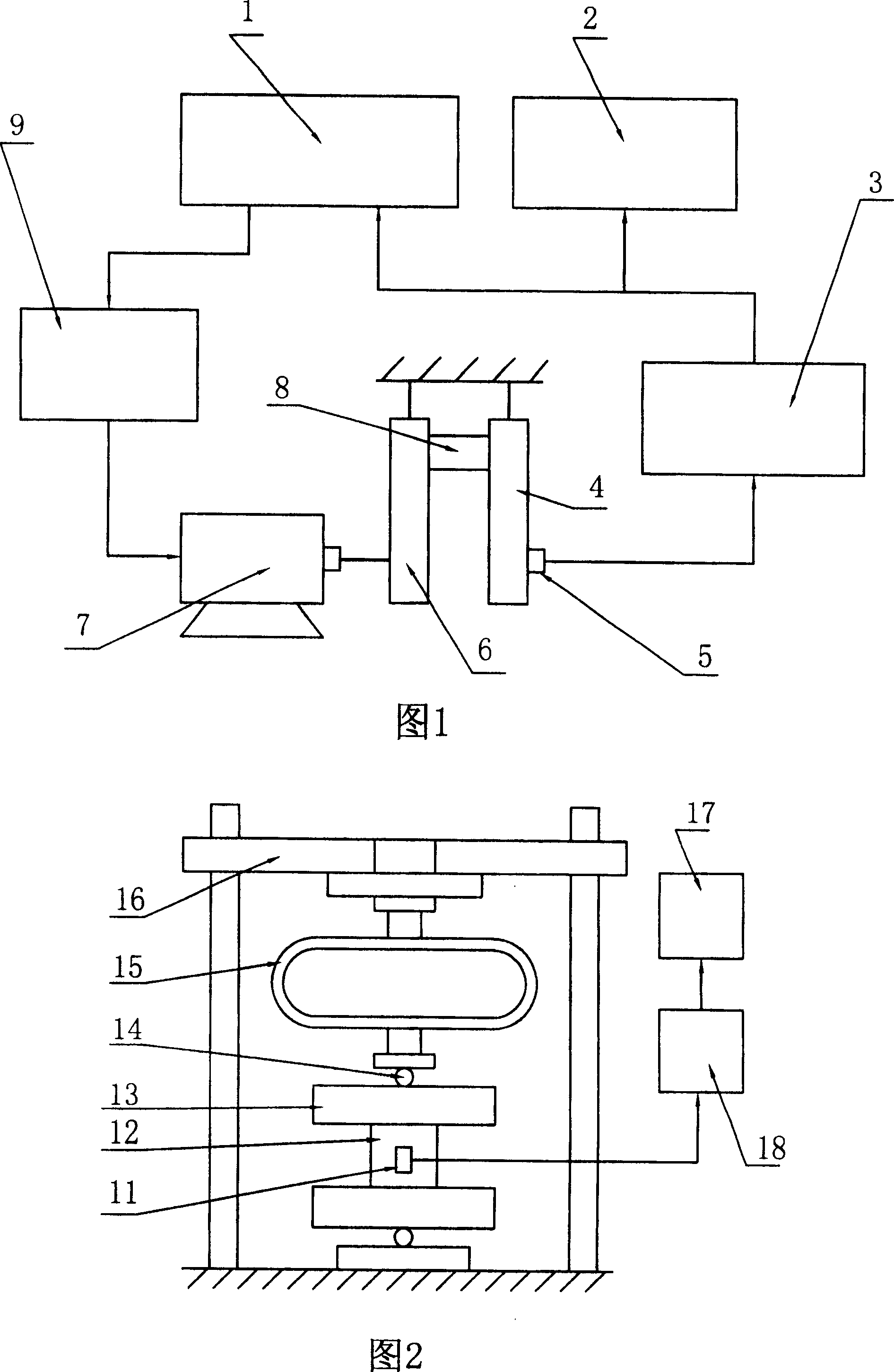
[0019] As shown in FIG. 2 , the instruments and equipment used mainly include strain gauges 11 , force gauges 15 , digital voltmeters 17 and strain gauges 18 . The resonant system composed of the test piece 12 and the swing arm 13 is placed flat on the iron base plate and leveled. The dynamometer 15 is connected in series between the screw rod of the loading device 16 and the force acting point on the swing arm 13. The dynamometer 15 and The swing arm 13...


PUM


Abstract

The invention relates to a method for measuring dynamic bending moment, which uses the strain as intermediate quantity and uses the principle of measuring the static mark dynamically to demarcate loading, equals the static and dynamic strain caused by the test sample according to the equal static and dynamic bending moment, demarcate dynamic loading based on the static loading through the strain, including two steps: demarcating the static loading and calibrating the dynamic loading. Said method solves the problem of which the bending moment cannot measure and display directly in the resonant bending fatigue testing device, the inaccuracy of dynamic bending moment is not more than 2%.

Description

technical field [0001] The invention belongs to the technical scope of fatigue test, in particular to a method for measuring dynamic bending moment. Background technique [0002] Bending moments are widely used in materials and testing as a form of loading. But so far, the measurement and display of the bending moment are all indirect methods, that is, obtained by calculating the product of the force and the moment arm, where the force is the measured. At present, there is no testing machine that can directly measure and display the bending moment, especially the resonant bending moment fatigue test device. Not only is the measurement and control of the bending moment more difficult, but also the error is large, which is difficult to meet the needs of the test work. As shown in Figure 1, it is a typical resonant bending fatigue test device, which is mainly composed of a vibration controller 1, a vibrator 7, a resonant system composed of a swing arm 4 symmetrically fixed at ...

Claims


Application Information

Patent Timeline
Patent Type & Authority Patents(China)
IPC IPC(8): G01N3/32G01N3/00
Inventor 冯美斌
Owner DONGFENG MOTOR CORP HUBEI
Why Eureka
Try Eureka