
Parallelism degree detecting device

A detection device and parallelism technology, applied in angle/taper measurement and other directions, can solve problems such as low efficiency, impracticality, and low efficiency, and achieve the effects of high measurement efficiency, convenient and intuitive measurement, and simple structure

Inactive Publication Date: 2015-07-08
NINGBO GREEN SOURCE GARDEN TOOLS
View PDF7 Cites 0 Cited by
  • Summary
  • Abstract
  • Description
  • Claims
  • Application Information

AI Technical Summary

Problems solved by technology

At present, there are mainly manual and automatic methods for detecting the parallelism of two planes. The manual method is to use vernier calipers or micrometers to measure the distance between the two planes of the workpiece to be measured, and calculate according to the measured data. The parallelism of the measured workpiece, and finally judging whether the measured workpiece is a qualified product, is time-consuming, laborious, and inefficient; the automatic method is mostly carried out under the three-dimensional coordinate measuring machine, and the probe of the three-dimensional coordinate measuring machine is used to touch the workpiece. After finishing the data of the points on one side, turn it over to measure the other side, and then re-fit the two planes in the computer according to these points, and further evaluate the parallelism of the two planes. The same efficiency is low and the cost is high. For some For the measurement of workpieces that strictly require the parallelism of the upper and lower planes, this method of measurement is not very practical

Method used


Image

  • Parallelism degree detecting device
  • Parallelism degree detecting device

Examples


Embodiment Construction

[0009] The present invention will be further described in detail below in conjunction with the accompanying drawings and embodiments.

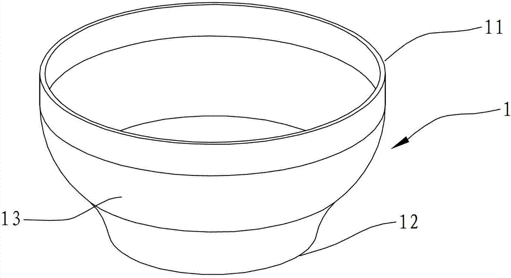
[0010] see figure 1 and figure 2 , a parallelism detection device for measuring whether the upper and lower surfaces of a workpiece 1 to be tested are parallel. The workpiece 1 to be tested is bowl-shaped and includes an upper surface 11 , a lower surface 12 and a main body 13 between the upper surface 11 and the lower surface 12 .

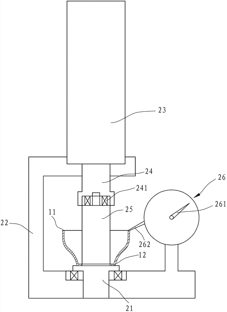
[0011] The parallelism detection device comprises a lower pallet 21, the upper plane of the lower pallet 21 is a horizontal plane, the workpiece 1 to be measured is placed on the upper surface of the lower pallet 21, and its lower surface 12 contacts with the upper plane of the lower pallet 21. The lower tray 21 is placed on the lower part of the bracket 22, the upper part of the bracket 22 is fixed with a cylinder 23, the lower part of the cylinder 23 is provided with a piston 24, the lower part of the piston ...


PUM


Abstract

The invention discloses a parallelism degree detecting device. The parallelism degree detecting device is characterized by comprising a lower tray with a horizontal upper surface, wherein the upper surface of the lower tray is provided with a workpiece to be detected, the lower surface of the workpiece to be detected is in contact with the upper surface of the lower tray, the workpiece to be detected is internally and fixedly provided with an upper top rod which can be rotated, a measuring meter is arranged at the position close to the workpiece to be detected, a probe of the measuring meter is in contact with the upper surface of the workpiece to be detected and moves vertically along the upper surface of the workpiece to be detected when the workpiece to be detected is in rotation, and the measuring meter is also provided with a pointer which can be used for displaying data of the up-and-down moving of the probe. By arranging the probe on the upper surface of the rotating workpiece to be detected, the probe can move vertically along the upper surface when meeting the upper surface and lower surface which are unparallel, the movement can be displayed on the measuring meter through the pointer, the structure is simple, the measuring is convenient and direct, and the measuring efficiency is high.

Description

technical field [0001] The invention relates to a detection device, in particular to a device for detecting the parallelism of workpiece planes. Background technique [0002] Parallelism refers to the degree to which two planes or two lines are parallel. At present, there are mainly manual and automatic methods for detecting the parallelism of two planes. The manual method is to use vernier calipers or micrometers to measure the distance between the two planes of the workpiece to be measured, and calculate according to the measured data. The parallelism of the measured workpiece, and finally judging whether the measured workpiece is a qualified product, is time-consuming, laborious, and inefficient; the automatic method is mostly carried out under the three-dimensional coordinate measuring machine, and the probe of the three-dimensional coordinate measuring machine is used to touch the workpiece. After finishing the data of the points on one side, turn it over to measure th...

Claims


Application Information

Patent Timeline
Patent Type & Authority Patents(China)
IPC IPC(8): G01B5/24
Inventor 李军峰
Owner NINGBO GREEN SOURCE GARDEN TOOLS
Learn More