Air duct system, air supply method thereof, fan with air duct system and air conditioner with air duct system

A technology for air conditioners and air ducts, applied in the field of air ducts, which can solve the problems of low air output efficiency and achieve stable air volume, good effect, energy saving and environmental protection

Inactive Publication Date: 2015-02-25
GD MIDEA AIR-CONDITIONING EQUIP CO LTD
View PDF5 Cites 8 Cited by
  • Summary
  • Abstract
  • Description
  • Claims
  • Application Information

AI Technical Summary

Problems solved by technology

[0002] In the air duct structure in the prior art, grid-shaped air inlets and outlets are directly arranged on the casing, and the air outlet efficiency is low

Method used


Image

  • Air duct system, air supply method thereof, fan with air duct system and air conditioner with air duct system
  • Air duct system, air supply method thereof, fan with air duct system and air conditioner with air duct system
  • Air duct system, air supply method thereof, fan with air duct system and air conditioner with air duct system

Examples


Embodiment 1

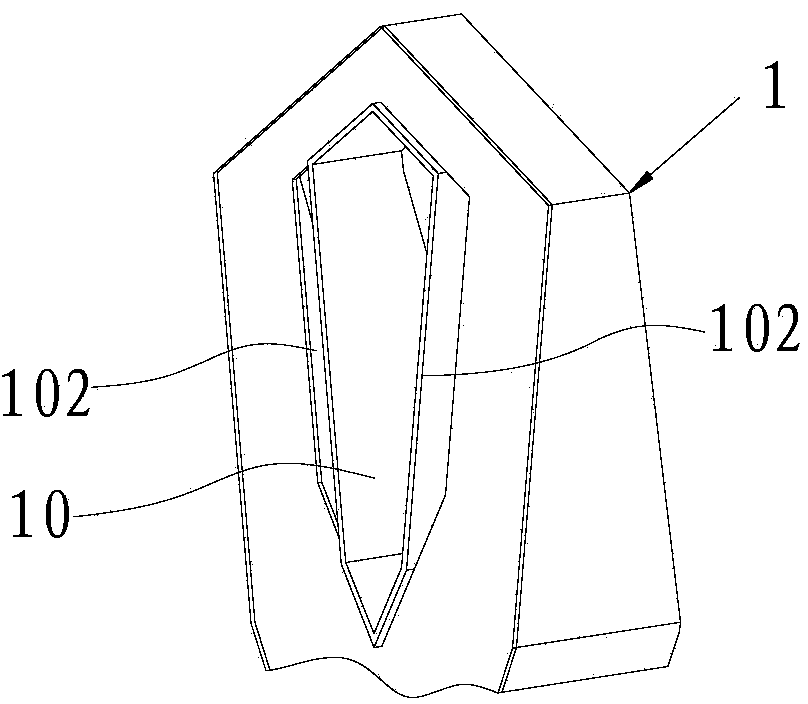
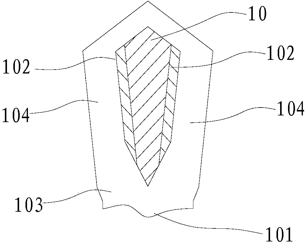
[0059] like figure 1 and figure 2 As shown, the air duct system provided by the embodiment of the present invention can be applied to the fields of fans, air conditioners and other products. The above-mentioned air duct system includes a casing 1 with an airflow channel 103 , the casing 1 has at least one air inlet 101 and at least two air outlets 102 , and both the air inlet 101 and the air outlet 102 communicate with the airflow channel 103 . A wind tunnel 10 penetrating through the casing 1 is provided between at least two air outlets 102 , and the air flow channel 103 includes flow channels 104 respectively communicating with each air outlet 102 . The air flow is divided into at least two streams, and blown out from the air outlets 102 on both sides of the wind tunnel 10 through the split channel 104 . The cross-section of the wind tunnel 10 can be circular, polygonal, elliptical, special-shaped, etc. In this embodiment, the wind tunnel 10 can be irregular rhombus or th...

Embodiment 2

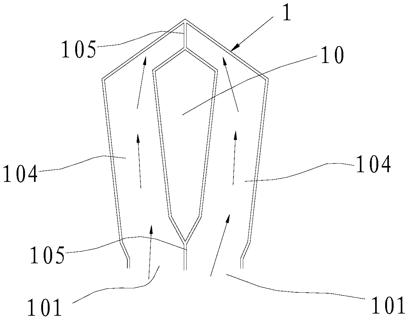
[0063] On the basis of Embodiment 1, in this embodiment, as image 3 As shown, the runners 104 on both sides of the same wind tunnel 10 are independent of each other, that is, two or more runners 104 are separated by a partition 105 throughout, that is, the runners 104 are in an independent state.

Embodiment 3

[0065] On the basis of Embodiment 1, in this embodiment, as Figure 4 As shown, any ends of the runners 104 on both sides of the same wind tunnel 10 are connected to each other; that is, the starting ends of two or more runners 104 are connected to each other, and after passing through the side walls of the corresponding wind tunnel 10, each runner The ends of 104 are separated by partition 105 . like Figure 5 As shown, the start ends of two or more flow channels 104 can also be separated by a partition 105, and the ends of two or more flow flow channels 104 are connected, that is, the flow flow channels 104 are in a semi-independent state.


PUM


Abstract

The invention belongs to the technical field of air ducts, and discloses an air duct system, an air supply method of the air duct system, a fan with the air duct system and an air conditioner with the air duct system. Airflow is at least divided into two ways and blown out from air outlets in the two sides of an air tunnel through flow diversion passages, so that airflow moving forwards evenly and stably is formed on the two sides of the air tunnel, strong and stable negative pressure can be generated in the air tunnel, under the suction effect of the negative pressure, air at the rear of the air tunnel is sucked forwards, enters the air tunnel from the rear end of the air tunnel, penetrates through the air tunnel, and then flows out of an opening in the front end of the air tunnel, the air supply effect of an airflow center is enhanced, air surrounding the air tunnel is supplemented due to the effect of the negative pressure, the center airflow drives the airflow surrounding the center airflow to move forwards together, the air supply range is increased, based on the aerodynamics principle, the air supply effect that the air inflow capacity is multiple times of the air inflow capacity of air inlets is formed, the energy efficiency utilization rate is high, and the air supply effect is good.

Description

technical field [0001] The invention belongs to the technical field of air ducts, and in particular relates to an air duct system and an air supply method thereof, a fan and an air conditioner provided with the air duct system. Background technique [0002] In the air duct structure in the prior art, grid-shaped air inlets and outlets are directly arranged on the casing, and the air outlet efficiency is low. Contents of the invention [0003] The object of the present invention is to overcome the shortcomings of the above-mentioned prior art, and provide an air duct system and its air supply method, a fan and an air conditioner with the air duct system, which have high air outlet efficiency. [0004] The technical solution of the present invention is: an air duct system, comprising a housing with an air flow channel, the housing has an air inlet and at least two air outlets, and at least two air outlets are provided with a through hole between the air outlets. In the wind...

Claims


Application Information

Patent Timeline
Patent Type & Authority Applications(China)
IPC IPC(8): F24F13/02F24F13/30
CPCF24F13/0236F24F13/30
Inventor 华龙
Owner GD MIDEA AIR-CONDITIONING EQUIP CO LTD
Why Eureka
Try Eureka