Blowing device

An air supply device, propeller fan technology, applied in clothing, helmets, helmet covers, etc., can solve the problems of unable to obtain stable air supply effect, unstable shape of air flow path, etc., to reduce the reduction and reduction of air supply efficiency. Small air resistance, stable air supply effect

Inactive Publication Date: 2017-06-20
TJM DESIGN CORP
View PDF3 Cites 0 Cited by
  • Summary
  • Abstract
  • Description
  • Claims
  • Application Information

AI Technical Summary

Problems solved by technology

That is, there is a problem that the shape of the air flow path inside the bag-shaped body is not stable, so that a stable air blowing effect cannot be obtained.

Method used


Image

  • Blowing device
  • Blowing device
  • Blowing device

Examples


Embodiment Construction

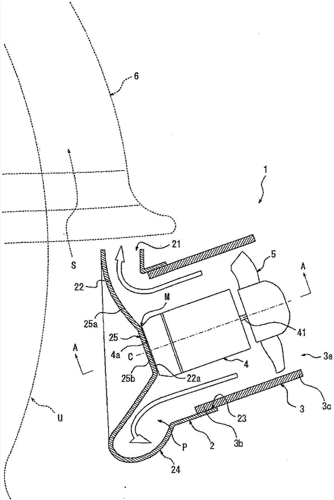
[0030] Hereinafter, embodiments of the present invention will be described by way of example with reference to the accompanying drawings. exist figure 1 An air blower 1 according to an embodiment of the present invention shown in , includes a nozzle portion 2 , a duct portion 3 , a motor 4 , and a propeller fan 5 , and the air blower 1 is mounted on a helmet 6 for use.

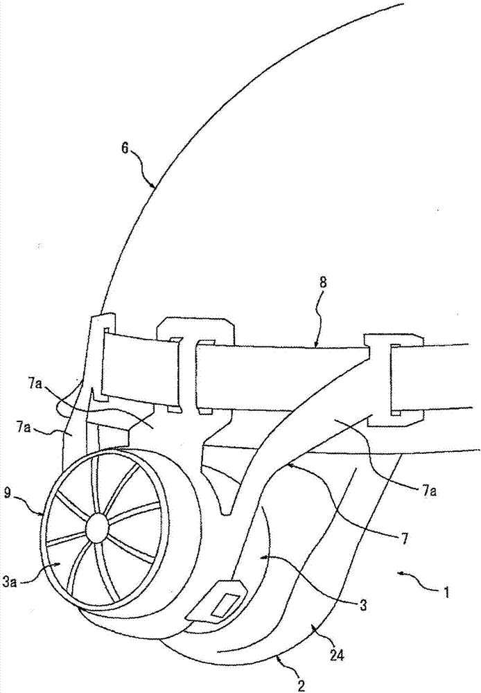
[0031] There is no particular limitation to the unit that the air blower 1 is assembled on the head cover 6, such as figure 2 As shown, the air blower 1 can be assembled using the mounting member 7 mounted on the duct portion 3 and the rubber band 8 for fixing the mounting member 7 to the head cover 6 . In order to improve the stability in the state in which the air blower 1 is attached to the head cover 6, it is preferable that the attachment member 7 has three or more connection arm parts 7a as shown in figure. In addition, a cover body 9 provided with a filter for removing dust or the like may be attache...


PUM


Abstract

The present invention provides a blowing device capable of reducing the air supply efficiency by reducing the air resistance and achieving a continuously stable air blowing effect. The air supply device (1) according to the present invention includes a nozzle portion (2) formed with a main opening (21) for conveying air to the space (S) in the hood, and a space (S) is held between the head cover (6) and the head of the user (U), and the nozzle portion (2) is held along the peripheral edge of the head cover (6); the tubular pipe portion (3) (4) which is held in the inside of the pipe portion (3); and a propeller fan (5) fixed to the rotation shaft (41) of the motor (4), the motor (4) (3c) is formed on the other end (3c) side of the pipe portion (3), and an inner portion of the nozzle portion (2) and the pipe portion (3) is formed inside the nozzle portion (2) and the pipe portion (3) (P) connected to the main opening (21), a flow path restricting portion (25) for reducing or closing the rear space (M) of the motor in the air flow path (P), the rear space (M) of the motor, Is formed between the motor (4) and the motor (4) Between the inner surface of the sidewall (22) opposite the nozzle portion (2) of (22a).

Description

technical field [0001] The invention relates to an air supply device assembled on a hood. Background technique [0002] In environments such as construction sites and construction sites, hoods are used to ensure safety. However, when working outdoors in summer, the internal temperature of the hoods worn on the head rises, and the humidity also increases due to sweating of workers. . Therefore, for example, the inside of the hood is in a high-temperature and high-humidity state, which brings discomfort to the worker, resulting in a decrease in work efficiency, or the problem that the field of vision is restricted due to sweat getting into the eyes. [0003] In order to solve such a problem, for example, Patent Document 1 describes an invention in which a fan is mounted on a hood and used. According to this fan, it is possible to cool the back of the neck or the back of the head of the user by blowing the wind from the air blower equipped on the hood to the user's back of th...

Claims


Application Information

Patent Timeline
Patent Type & Authority Applications(China)
IPC IPC(8): A42B3/28
CPCA42B3/286
Inventor 务台豊渡边和也筱崎勇也
Owner TJM DESIGN CORP
Why Eureka
Try Eureka