Anchor mechanism and cable rock bolt

An anchor cable and expander technology, applied in the field of rock anchor cable and rock bolt, to achieve the effect of an effective installation process

Active Publication Date: 2015-02-25
SANDVIK INTELLECTUAL PROPERTY AB
View PDF8 Cites 1 Cited by
  • Summary
  • Abstract
  • Description
  • Claims
  • Application Information

AI Technical Summary

Problems solved by technology

[0016] Thus, machine installation of anchor cables may allow installation of anchor rods of different lengths, but the installation still has the same problems as described above, whereby the attachment of the end fittings to the anchor cables is difficult once the cement grout has partially or fully cured. happens as a second operation

Method used


Image

  • Anchor mechanism and cable rock bolt
  • Anchor mechanism and cable rock bolt
  • Anchor mechanism and cable rock bolt

Examples


Embodiment Construction

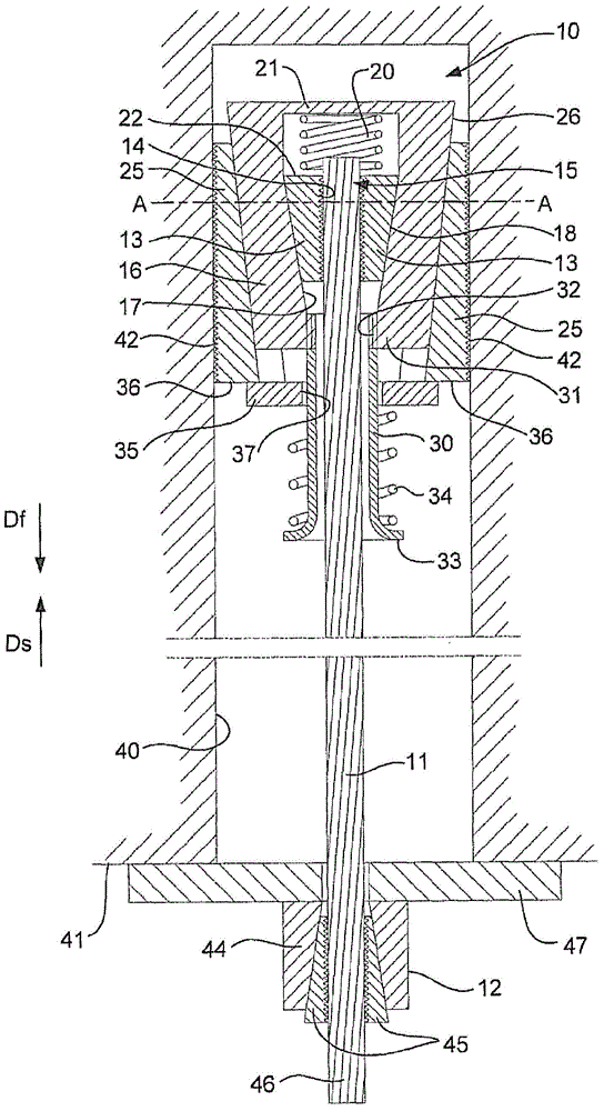
[0070] refer to figure 1 and 2 , showing the dilator mechanism 10, and at figure 1 In , the mechanism 10 is shown attached to the front end of the cable 11 . Lasso 11 in figure 1 is shown as disconnected between the dilator mechanism 10 and the tensioning device 12 . The actual length of the cable 11 can be from 2m to 15m, but longer or shorter lengths are possible.

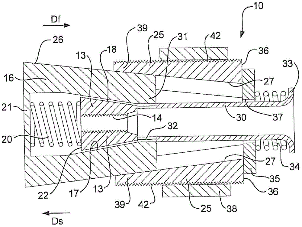
[0071] First refer to figure 2 , the dilator mechanism 10 includes a plurality of cable gripper elements 13 capable of image 3 and 4 See each section view of . The gripper elements 13 are identical to each other and are formed as circular segments and are dimensioned so that when the gripper elements 13 firmly grip the outer side surface of the cable 11, as figure 1 As shown, the gap G between the facing edges of the element 13 (see image 3 )reserve.

[0072] Such as figure 1 and 2 As shown, the gripper element 13 defines a central hole 14 into which the front end 15 of the cable 11 can be inserted...


PUM


Abstract

An expander mechanism 10 and a cable bolt, in which the expander mechanism includes gripper elements 13 which define a central bore 14 into which a cable end 15 can be inserted. A housing 16 houses the elements 13 and the housing 16 and the elements 13 cooperate slidingly along facing inclined surfaces 17, 18 so that relative movement increases or decreases the diameter of the central bore 14. A plurality of expander elements 25 cooperate slidingly against an outside surface 26 of the housing 16, so that movement of the housing 16 relative to the expander elements 25 can shift the expander elements 25 radially outwardly. The housing 16 has front and rear ends 21, 31 and an opening 32 formed in the rear end 31 to allow insertion of the cable 1 1 to enter the central bore 14 of the gripper elements 13. A biasing arrangement 34 acts between the housing 16 and the expander elements 25 to bias the expander elements 25 in a direction relative to the housing 16. A cable bolt including an expansion mechanism 10 is also provided.

Description

technical field [0001] The present invention relates to rock bolts suitable for stabilizing rock walls and faces, such as are used in the underground mining and roadway industries. The present invention relates to cable rock bolts employing flexible stay cables and a mechanical spreader at the front end of the stay cables for anchoring or assisting anchoring of rock bolts in places in which the bolts have been installed. drilling. Background technique [0002] The following discussion of the background of the invention is intended to facilitate an understanding of the invention. It should be understood, however, that the discussion is not an acknowledgment or admission that any of the material referred to was published, known or part of the common general knowledge as at the priority date of the application. [0003] Rock bolts for underground mining include solid rod rock bolts and rock bolts. The solid rod rock bolt adopts a rigid rod or rod, and since the rod is rigid,...

Claims


Application Information

Patent Timeline
Patent Type & Authority Applications(China)
IPC IPC(8): E21D21/00
CPCE21D2021/006E21D21/008E21D21/006
Inventor 米奇斯瓦夫·劳陶伊
Owner SANDVIK INTELLECTUAL PROPERTY AB
Why Eureka
Try Eureka