Narrow gap/ultra-narrow gap gas shielded welding automatic welding torch and manufacturing method thereof

A gas shielded welding, narrow gap technology, applied in the direction of manufacturing tools, electrode characteristics, welding equipment, etc., can solve the problems of reduced welding production cost, complex welding torch system, decreased welding current stability, etc., to achieve the conductive cross-sectional area and heat dissipation area. The effect of large, simplified welding torch structure and reduced manufacturing difficulty

Active Publication Date: 2016-05-25
武汉纳瑞格智能设备有限公司
View PDF12 Cites 0 Cited by
  • Summary
  • Abstract
  • Description
  • Claims
  • Application Information

AI Technical Summary

Problems solved by technology

The above-mentioned prior art also has the following limitations: 1. It is difficult to arbitrarily change the size and shape of the cross-section of the flow channel due to thick-walled pipes, and there are many brazed joints with complex structures and high manufacturing costs; 2. It is difficult to rotate and bend the contact tip. To reduce the groove assembly gap to an ideal state, the welding torch system is complex, and the carbon brush scheme for large current conduction requires extremely high conductive reliability technical measures; 3. The existence of flux strip technology has led to a significant increase in the complexity of process technology and equipment increase, the slag cleaning is difficult and the probability of slag inclusion defects increases, and the application of large and thick plates is difficult; 4. The nozzle is located outside the groove. When the plate thickness is greater than a certain thickness, large metallurgical protection must be used to achieve good metallurgical protection. Shielding gas with high flow rate and wide range will bring a large gas consumption, and the larger the thickness of the weldment, the more prominent the limitation, and it is very unfavorable for the reduction of welding production costs; Large, the metallurgical protection effect of the welding area is difficult to achieve the ideal state, and the thickness of the welding torch is difficult to reduce to a thinner value; 6. The water cooling structure is located outside the groove. When the thickness of the weldment is large, only the conductive tip is used to transfer heat to the groove External heat dissipation makes it difficult to ensure that the temperature rise of the contact tip is controlled in an ideal state, so this welding torch can only be used in the field of medium and thick plates that do not need the contact tip to fully extend into the groove, followed by the twin-wire eutectic pool, although it can be greatly improved Increase the deposition speed, but the heat input is large, not suitable for welding high-alloy steel and quenched and tempered high-strength steel; 7 is a split interconnection structure, the manufacturing is complicated and the overall rigidity is poor, there is no water cooling system, and it conducts electricity under long working cycles The temperature rise of the nozzle will lead to a decrease in the stability of the welding current; 8 is a split interconnection structure, the overall rigidity is poor, and the air guide structure is difficult to obtain efficient cooling and heat dissipation, and it is difficult to solve the problem of fusion of the side wall under the assembly gap of the wide welding groove; 9 Only involves a cylindrical contact tip and nozzle structure at the working end of the narrow gap welding torch, and does not involve the main structure of the narrow gap gas shielded welding (MAG / MIG) welding torch such as gas guide, guide wire, cooling, high temperature insulation, etc.
[0004] In addition to the above-mentioned limitations in the prior art, the common limitations are: the overall rigidity of the split-type interconnection structure is poor, and the manufacturing is difficult; This important function fails to achieve high efficiency and high reliability at the same time; especially according to different weldment materials, different weldment plate thicknesses, and different weld bead levels, only the replacement of accessories under the same welding torch body It can realize different side wall fusion control methods and meet different ultra-narrow gap gas shielded welding (MAG / MIG) welding process requirements, just like a narrow gap gas shielded welding (MAG / MIG) welding torch body, which can meet wide The double-pass process per layer under the welding groove assembly gap (G≈10mm) can also meet the single-pass process per layer under the ultra-narrow gap (G=5mm~7mm), which has not been seen in the existing technology

Method used


Image

  • Narrow gap/ultra-narrow gap gas shielded welding automatic welding torch and manufacturing method thereof
  • Narrow gap/ultra-narrow gap gas shielded welding automatic welding torch and manufacturing method thereof
  • Narrow gap/ultra-narrow gap gas shielded welding automatic welding torch and manufacturing method thereof

Examples


Embodiment 1

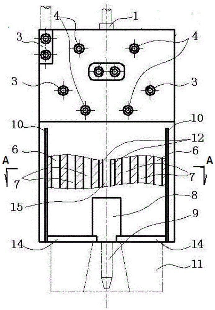
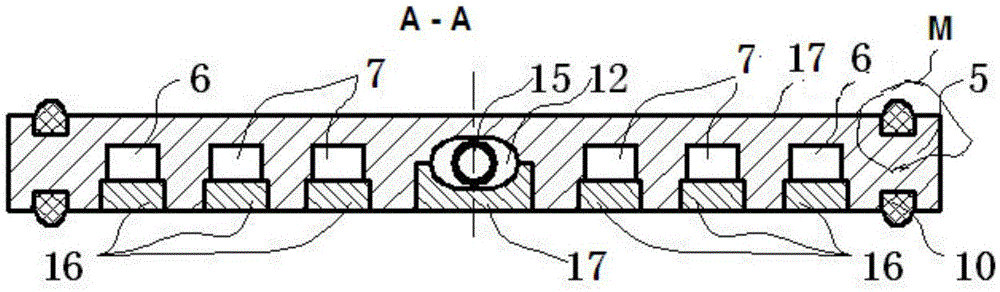
[0051] Example 1: Such as figure 1 As shown in Fig. 7, it is a basic embodiment of the automatic welding torch for narrow gap / ultra-narrow gap gas shielded welding of the present invention. It includes a plate-type welding torch body 5; the plate-type welding torch body 5 is internally integrated with a guide wire channel 12, a circulating water cooling flow channel 7 and a secondary protective air flow channel 6, and the upper part of the plate-type welding torch body 5 is fixedly connected with a primary protective gas inlet seat 2 and the secondary protective gas inlet seat 3, the water inlet / return water pipe seat 4 and the welding cable 13, the lower part of the plate welding torch body 5 is fixedly connected with a gas distribution device 8, and the gas distribution device 8 is assembled with the contact nozzle seat 18 and passed through The mortise on both sides of the shunt device 8 is fixed to the lower part of the plate torch body 5 through the body / nozzle conn...

Embodiment 2

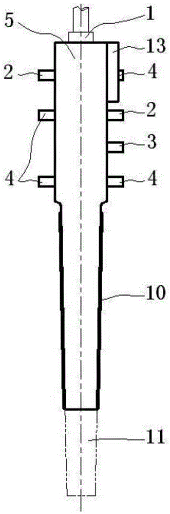
[0052] Example 2: is a further example. In the narrow gap / ultra-narrow gap gas shielded welding automatic welding torch, the wire feeding hose connection assembly 1 is installed on the top of the plate torch body 5; , and communicate with the primary protection gas flow passage; the secondary protection gas intake seat 3 is installed on both sides of the primary protection gas intake seat 2 near the outside of the wide side of the plate welding torch body 5, and communicates with the secondary protection gas flow passage 6; The water / return water pipe seat 4 is installed close to both sides of the primary protective gas inlet seat 2, and communicates with the corresponding circulating cooling water flow channel 7; the gas distribution device 8 is installed at the lower end of the plate welding torch body 5. The guide wire channel 12 is located in the middle of the plate welding torch body 5, its upper end communicates with the wire feeding hose connection assembly 1, and ...

Embodiment 3

[0054] Example 3: Such as Figure 1-8 Shown is an embodiment of a combined narrow-gap / ultra-narrow-gap gas shielded welding automatic welding torch of the present invention. It is formed by connecting two automatic welding torches for narrow-gap / ultra-narrow-gap gas-shielded welding of single wires of the present invention; 5; The plate welding torch body 5 is internally integrated with a guide wire channel 12, a circulating water cooling flow channel 7 and a secondary protective gas flow channel 6, and the upper part is fixedly connected with a primary protective gas intake seat 2 and a secondary protective gas intake seat 3 , and the water inlet / return pipe seat 4 and the welding cable 13, the lower part is fixedly connected with a gas distribution device 8, the gas distribution device 8 is assembled with the contact tip seat 18, passes through the mortise on both sides of the distribution device 8, and passes through the body The / nozzle connection assembly 14 is fix...


PUM


Abstract

The invention relates to a multifunctional narrow-gap / ultra-narrow-gap gas shielded welding automatic welding torch and a manufacturing method thereof. The welding torch includes a plate-type welding torch body; the welding torch body is integrated with a guide wire channel, a circulating water cooling flow channel and a secondary protective air flow channel. There are primary shielding gas intake seat and secondary shielding gas intake seat, water inlet / return pipe seat and welding cable fixed, and a gas splitter device is fixedly connected to the lower part, which is fixed to the lower part of the plate welding torch body through the body / nozzle connection assembly . The steps of the method include: preparing raw materials, processing related parts, embedding and brazing runner groove cover plates, etc., embedding ceramic strips, spraying ceramic coatings on external components, and the like. The advantages of the present invention are: high integration, high-speed guide wire, stable and reliable conduction, gas conduction, high-efficiency heat dissipation, reliable insulation; long life; easy processing; low cost; good overall rigidity; The application of the gun is integrated; the work efficiency is high, safe and reliable.

Description

technical field [0001] The invention relates to a narrow gap / ultra-narrow gap gas-shielded welding automatic welding torch and a manufacturing method thereof, which is a multifunctional integrated overall plate-type narrow-gap / ultra-narrow gap gas-shielded welding (MAG / MIG) automatic welding torch designed and manufactured based on composite processing of plates. A welding torch belongs to the technical field of welding. Background technique [0002] With the rapid development of industrial equipment to high capacity, high parameters, and large scale, high reinforcement, thick wall and heavy equipment have become one of the important characteristics of modern equipment manufacturing. This will bring about a multiplied increase in the amount of welding work, which will lead to an increasingly prominent contradiction between the equipment manufacturing cycle and welding productivity. Significantly improving welding productivity has become an urgent requirement for technologic...

Claims


Application Information

Patent Timeline
Patent Type & Authority Patents(China)
IPC IPC(8): B23K9/28B23K9/173B23P15/00
CPCB23K9/173B23K9/1735B23K9/26B23K9/28B23K9/285B23P15/00
Inventor 张富巨张瑞
Owner 武汉纳瑞格智能设备有限公司
Why Eureka
Try Eureka