
Combination pipeline locker

A locking device and pipeline technology, applied in the direction of pipe supports, pipes/pipe joints/fittings, sliding valves, etc., can solve the problem that the locking pressure cannot be adjusted, the locking device and the main body are unreliable in swinging left and right, and the locking device cannot To facilitate disassembly and assembly and other issues, to achieve the effect of improving efficiency and reliability, improving efficiency and safety, improving aesthetics and standardization

Active Publication Date: 2017-07-18
刘明 +1
View PDF5 Cites 0 Cited by
  • Summary
  • Abstract
  • Description
  • Claims
  • Application Information

AI Technical Summary

Problems solved by technology

[0003] The purpose of this patent is to solve the situation that the current hitch device cannot lock the hitch object stably and reliably, the lock device cannot be easily disassembled and assembled, the lock pressure cannot be adjusted, and the left and right swing between the lock device and the main body is unreliable, etc.

Method used


Image

  • Combination pipeline locker
  • Combination pipeline locker
  • Combination pipeline locker

Examples


Embodiment

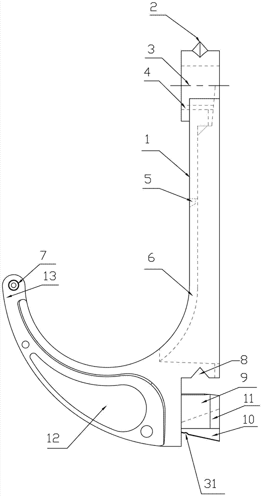
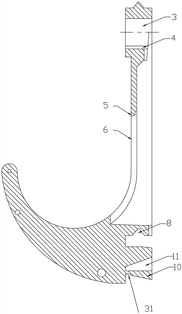
[0052] The combination pipeline locking device of the present invention is as Figure 1 to Figure 19 As shown, the top of the main body 1 of the combined pipeline locker has an anti-off block 2, a through hole 3 under the anti-off block 2, a through hole groove 4 on one side of the through hole 3, and a stop tooth 5 and a handcuff ring rail in the middle of the main body 1. Groove 6, limit teeth 5 are on one side of handcuff ring rail groove 6, and have certain angle and can prevent handcuff ring 14 from abdicating. There is a rotating shaft 7 on one side of the main body 1 . There is an anti-swing groove 8 under the main body 1, and there is a through column 9 under the anti-off groove 8. There is an elastic anti-sway block 10 on one side of the through column 9, and there is a space inside the through column 3 for the elastic anti-sway block 10 to move up and down. Return slot 11. There are reflective devices on both sides of the combination line locker.

[0053] The hand...


PUM


Abstract

The invention discloses a combination pipeline buckling device. The combination pipeline buckling device is characterized in that the main body of each combination pipeline buckling device can be independently fixed, hooking articles can be arranged on the combination pipeline buckling device in a hanging way after the combination pipeline buckling device is fixed, a rotating shaft chamber in each handcuffing ring can be pressed into a rotating shaft of the main body of each combination pipeline buckling device, holes in two sides of the handcuffing rings can be clamped on the rotating shaft of the main body of each combination pipeline buckling device, and the clamping and pressing strength can be regulated or the hooking articles can be loosened through handles on the handcuffing rings. Nameplate covers can be arranged on in-position grooves and nameplate grooves which are formed in the handcuffing rings, and information of related pipelines can be noted on the nameplate covers; the combination pipeline buckling device can be subjected to combined connection through through holes in each main body and through posts on each main body, a through hole groove is formed in one side of each through hole, one side of each through post is provided with an elastic anti-swing block, and the elastic anti-swing blocks on the through posts are clamped between reset grooves in the through posts and the through hole grooves in the through holes after installation. The combination pipeline buckling device disclosed by the invention is attractive and reliable, the combination is convenient and quick, the use is flexible, and the standardization degree is higher.

Description

technical field [0001] This patent relates to a device that is convenient for erecting and erecting cables, pipes and other hanging objects, especially a device that needs to have a locking function. Combined pipeline locker for functions and warning messages. Background technique [0002] At present, the hooking devices used in the installation of cables and pipes in industrial and mining enterprises cannot fix and lock the hooked objects conveniently and quickly, causing the hooked objects to loosen, fall off, etc. There are limitations, low efficiency of fixed installation, and unreliability. Contents of the invention [0003] The purpose of this patent is to solve the problems that the current hitch device cannot stably and reliably lock the hitch, the lock device cannot be easily and freely disassembled, the lock pressure cannot be adjusted, and the left and right swing between the lock device and the main body is unreliable. Designing a locking device is more relia...

Claims


Application Information

Patent Timeline
Patent Type & Authority Patents(China)
IPC IPC(8): F16K3/02
CPCF16L3/02
Inventor 刘明刘益辰郑铁辉朱金环朱玉兰
Owner 刘明
Learn More