Lantern lock

a technology of lanterns and locks, applied in the field of film and video production lighting, can solve the problems of hanging assembly, no means of positioning the lantern from below, from the side, or at any other angle, and the lamp is susceptible to undesirable swinging, so as to prevent the lamp from swinging

Active Publication Date: 2006-01-03
WATCHULONIS DANIEL
View PDF7 Cites 25 Cited by
  • Summary
  • Abstract
  • Description
  • Claims
  • Application Information

AI Technical Summary

Benefits of technology

[0008]The lantern lock is advantageous for several reasons. First, because the lantern lock is clampable, a lamp originally designed for hanging on a cord is positionable in any desired position. In addition, because the lantern lock fixes the lamp relative to the lock, the lamp is prevented from swinging.

Problems solved by technology

One problem with the current design of such lanterns is the hanging assembly.
This design is problematic for the film and video industries for several reasons.
First, it is oftentimes desirable to position the lantern in positions other than hanging from a fixed point of a ceiling.
However, no means exist for positioning the lantern from below, from the side, or at any other angle.
In addition, without additional stabilizing equipment, the lamp is susceptible to undesirable swinging due to its hanging configuration (for example, due to natural or artificial wind, or from people or objects unintentionally bumping into the lamp).

Method used


Image

  • Lantern lock
  • Lantern lock
  • Lantern lock

Examples


Embodiment Construction

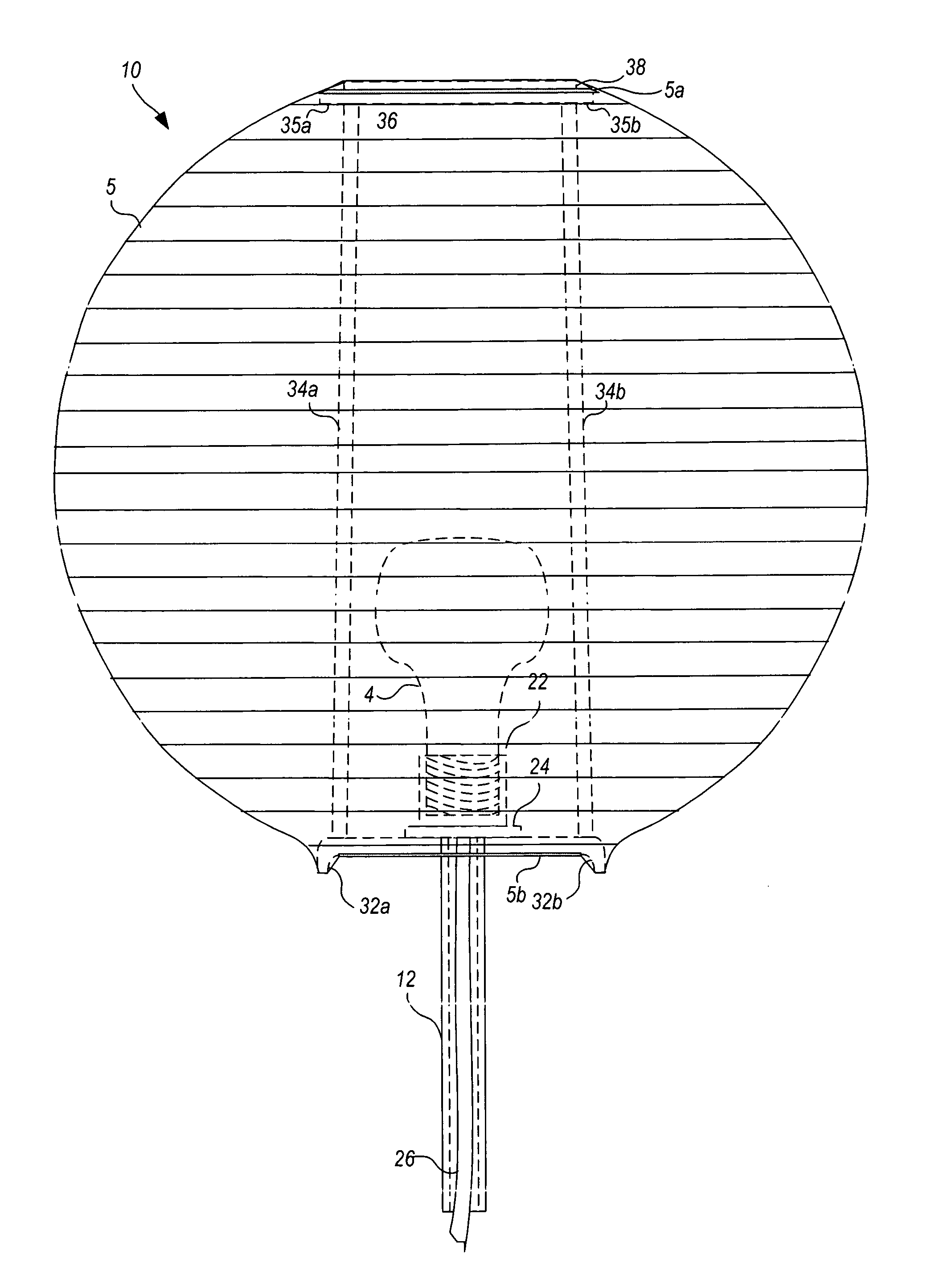
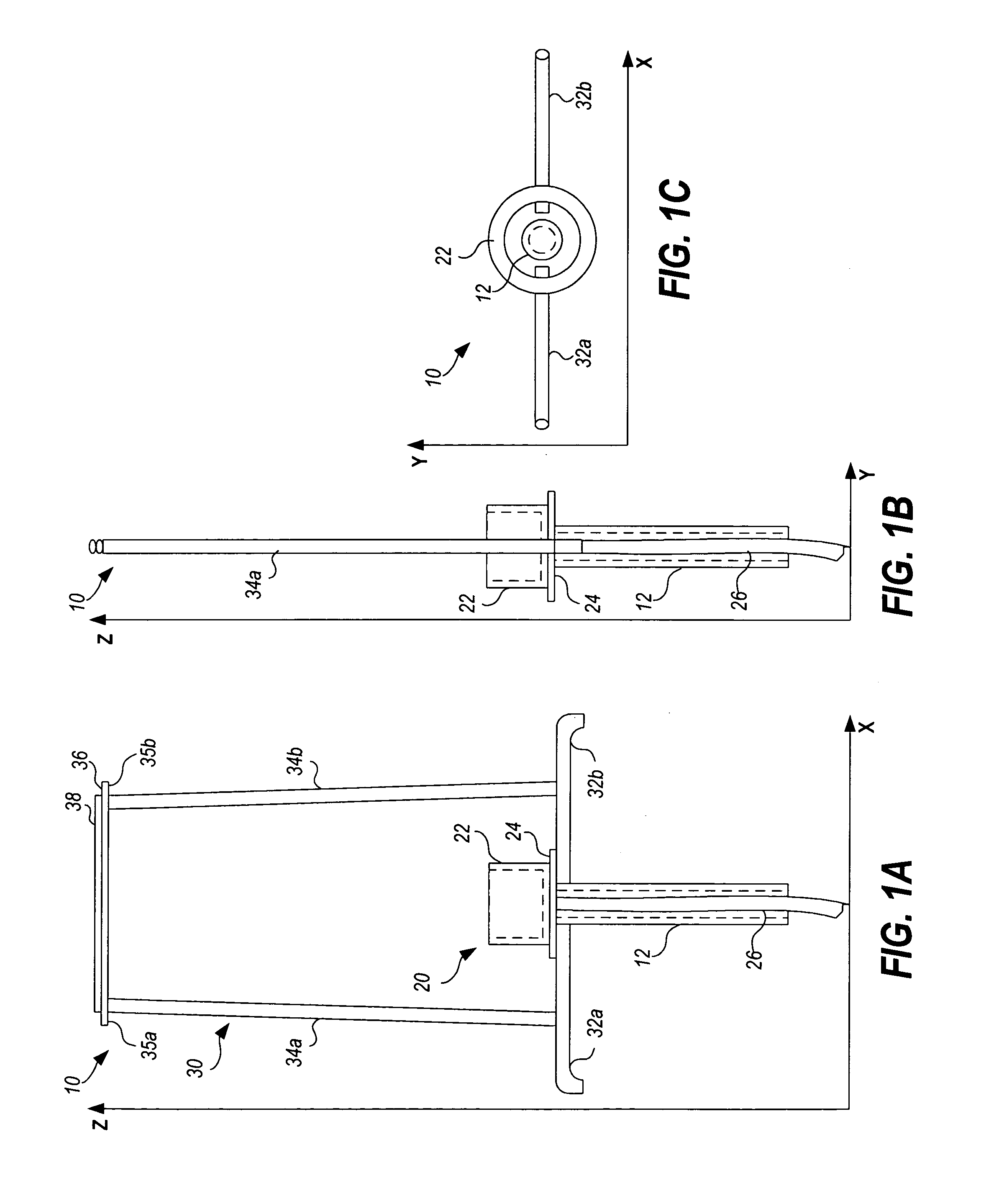
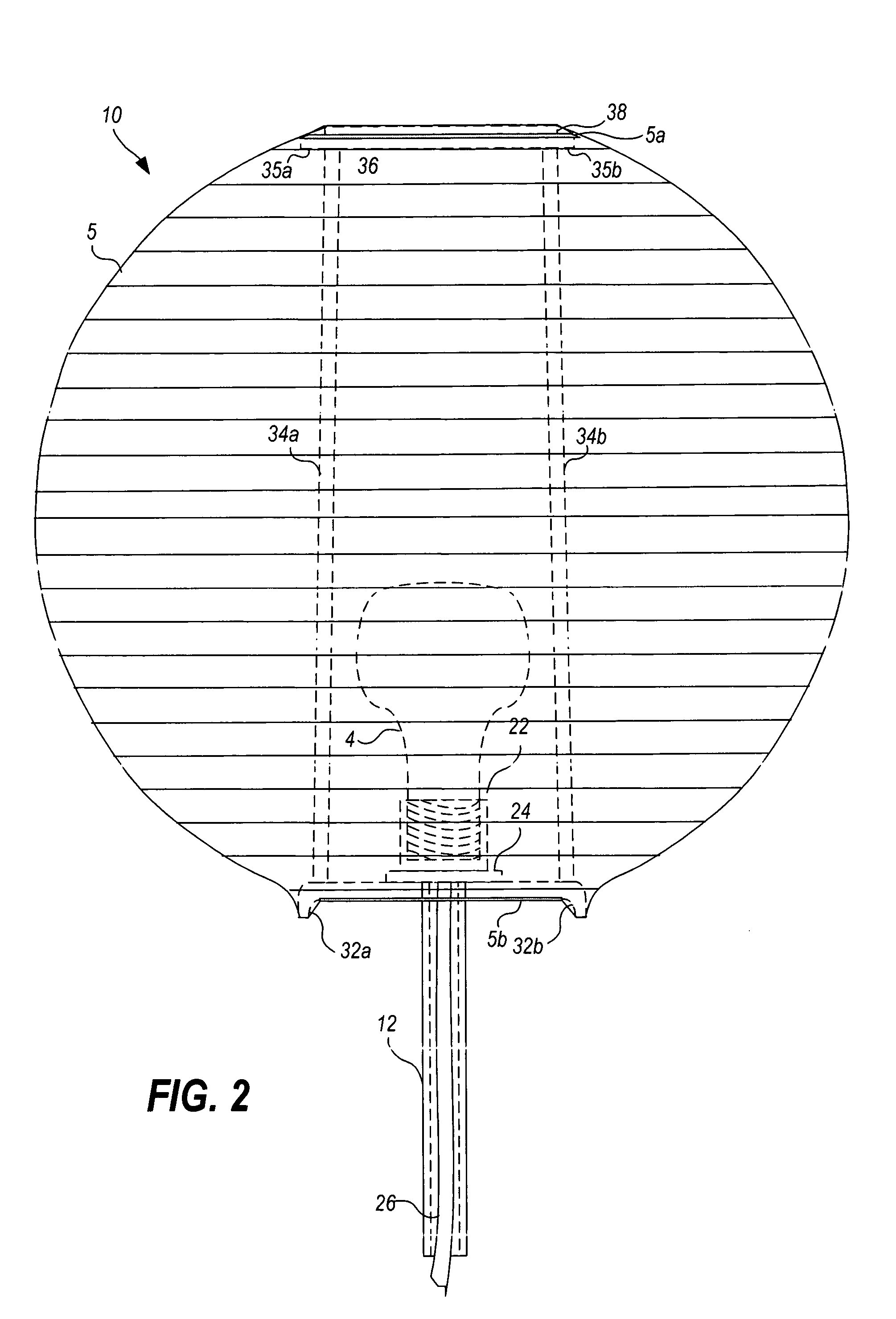
[0025]Turning now to the drawings, FIGS. 1A, 1B, and 1C illustrate a preferred embodiment of a lantern lock 10 implemented in accordance with the invention, showing the view of the x-z plane, the y-z plane, and the x-y plane, respectively. As illustrated, the lantern lock 10 includes a mounting stud 12 attached to a socket assembly 20. The socket assembly 20 includes a threaded light bulb socket 22 attached to a base 24 and a power cord 26 electrically attached to the socket 22. In the preferred embodiment, the mounting stud 12 is a hollow cylindrical tube, and the power cord 26 is threaded through the tube, which is welded to the base 24.

[0026]The lantern lock 10 also includes a spreading frame 30 fixedly attached to the mounting stud 12. In the preferred embodiment, the shade 5 (FIG. 2) to be mounted onto the spreading frame 30 is an accordion-style global shade having a material such as rice paper or cloth collapsibly attached to a plurality of concentric wire ring pairs. Accordi...


PUM


Abstract

A novel lantern lock for holding a light and its light shade in a fixed position when mounted on standard lighting equipment is presented. The lantern lock includes a socket assembly with a light bulb socket and power cord. A spreading frame is fixedly attached to the socket assembly, and when a shade is mounted thereon, holds the shade in a fixed position relative to the socket assembly. In one embodiment, the socket assembly is mounted on a base and mounting stud is physically attached to the socket assembly. In an alternative embodiment, a clamp clamps at least a portion of the socket assembly, and the mounting stud is attached to the clamp. The mounting stud is compatible with standard lighting equipment mounting devices, such as a C-clamp mountable on an extension arm of a C-stand. The C-clamp may be rotated in any position to fix the position of the mounting stud, and to thereby fix the position of the light.

Description

[0001]This application claims the benefit of priority from U.S. Provisional Patent Application Ser. No. 60 / 463,941 filed Apr. 18, 2003.BACKGROUND OF THE INVENTION[0002]The present invention relates generally to film and video production lighting, and more particularly to a lantern lock for locking a hanging-style lamp into a fixed but controllable position.[0003]Lamps are standard equipment in the film and video production industry. Different lighting is used for different purposes. Some productions require the use of diffused lighting. One way of achieving this effect is through the use of a lantern having an accordion-style shade (sometimes referred to as a “Chinese lantern”). As known by those in the lighting and film industries, an accordion-style shade lantern includes a shade having a material such as rice paper or cloth collapsibly attached to a plurality of ribs, which when fit over a lamp spreader, spread out to form an expanded lantern. The accordion-style lantern may take...

Claims


Application Information

Patent Timeline
Patent Type & Authority Patents(United States)
IPC IPC(8): F21V1/06
CPCF21V1/06F21V1/18F21V21/116F21W2131/406F21V21/14F21V17/06
Inventor WATCHULONIS, DANIEL
Owner WATCHULONIS DANIEL
Why Eureka
Try Eureka