Lockable pet door

a pet door and lock technology, applied in the field of lockable pet doors, can solve the problems of low placement of lock controls, and unfavorable pet owners with limited mobility or disabilities, and achieve the effect of reducing or eliminating unintentional adjustmen

Inactive Publication Date: 2005-11-01
RADIO SYST CORP
View PDF13 Cites 24 Cited by
  • Summary
  • Abstract
  • Description
  • Claims
  • Application Information

AI Technical Summary

Benefits of technology

[0013]The controls are generally located above the passageway. This makes the operation of the lock mechanism much more accessible to the pet owner than conventional controls that are integrated with the lock mechanism they operate and positioned at the bottom of the pet door, below the passageway. By placing the controls above the passageway, the animal using the pet door is unlikely to make incidental contact with the controls. This reduces or altogether eliminates unintentional adjustment of the pet owner's desired ingress and egress restrictions.
[0014]In addition, the lock mechanism includes a pair of bolts, each bolt connected to one of the controls via a linkage. The bolt is adapted to be move in and out of engagement with the flap and also a socket included in the flap. The locking mechanism generally operates in the following manner. As one of the controls is actuated, the linkage moves forcing the bolt to move. In a first position, the bolt is retracted and does not engage or otherwise obstruct movement of the flap. Moving the control to a second position results in the bolt engaging the flap but not the socket. In this position the flap is prevented from swinging in one direction while remaining free to swing in the opposite direction. When the control is moved to a third position, the bolt engages the socket effectively preventing the flap from swinging in either direction thereby restricting both ingress and egress.

Problems solved by technology

Further, due to the placement of the lock control, it is not easily accessible.
The low placement of the lock control presents a hardship for pet owners with limited mobility or disabilities.
The low placement of the lock controls subjects them to unintended manipulation, such as by incidental contact with the pet as the pet passes through the portal.
This can result in the pet accidentally locking the pet door.
However, such a lock mechanism requires pet owners to provide a key to each animal.
If the key is lost, such as when the collar becomes snagged and breaks, then the pet can not access the pet door.

Method used


Image

  • Lockable pet door
  • Lockable pet door
  • Lockable pet door

Examples


Embodiment Construction

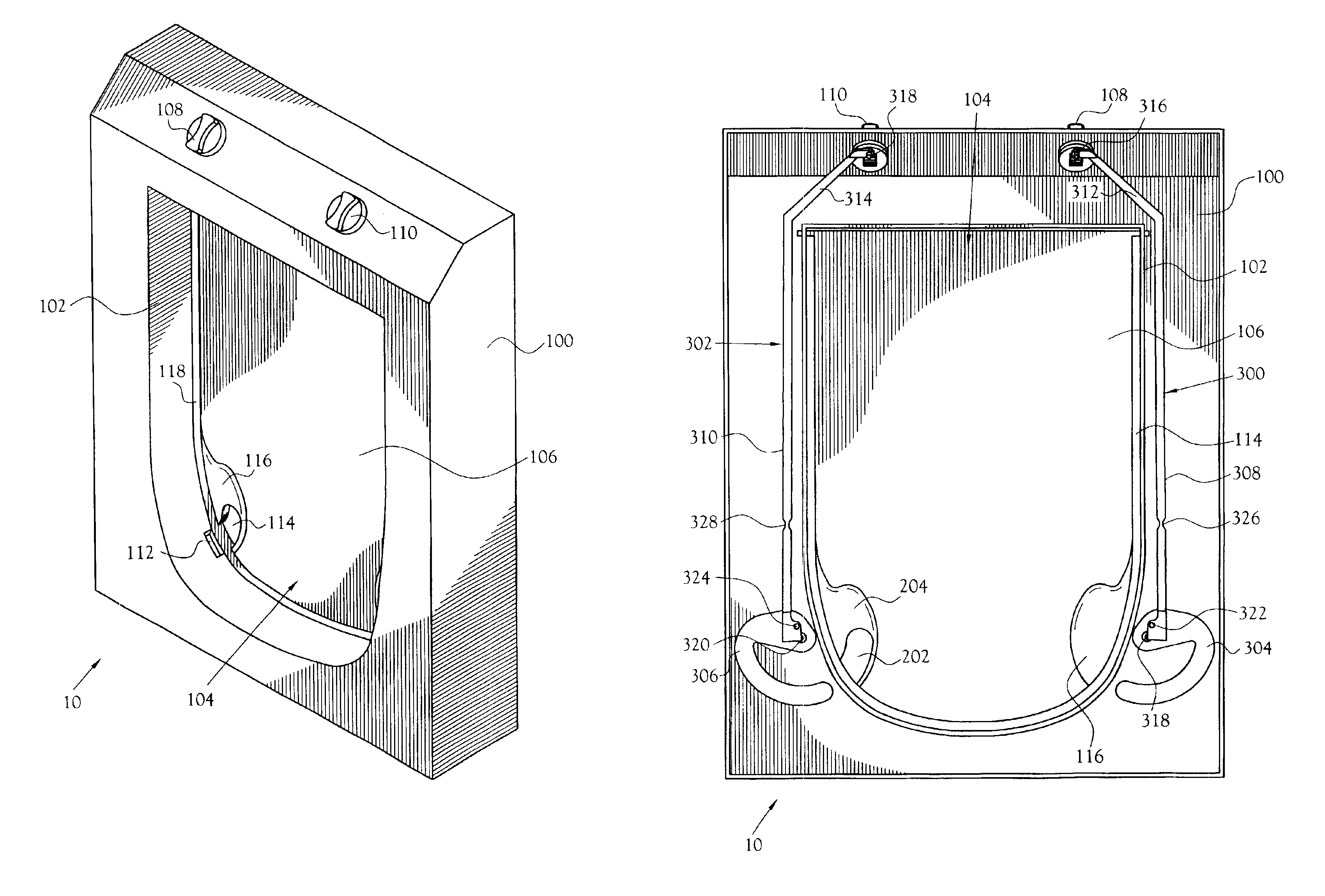
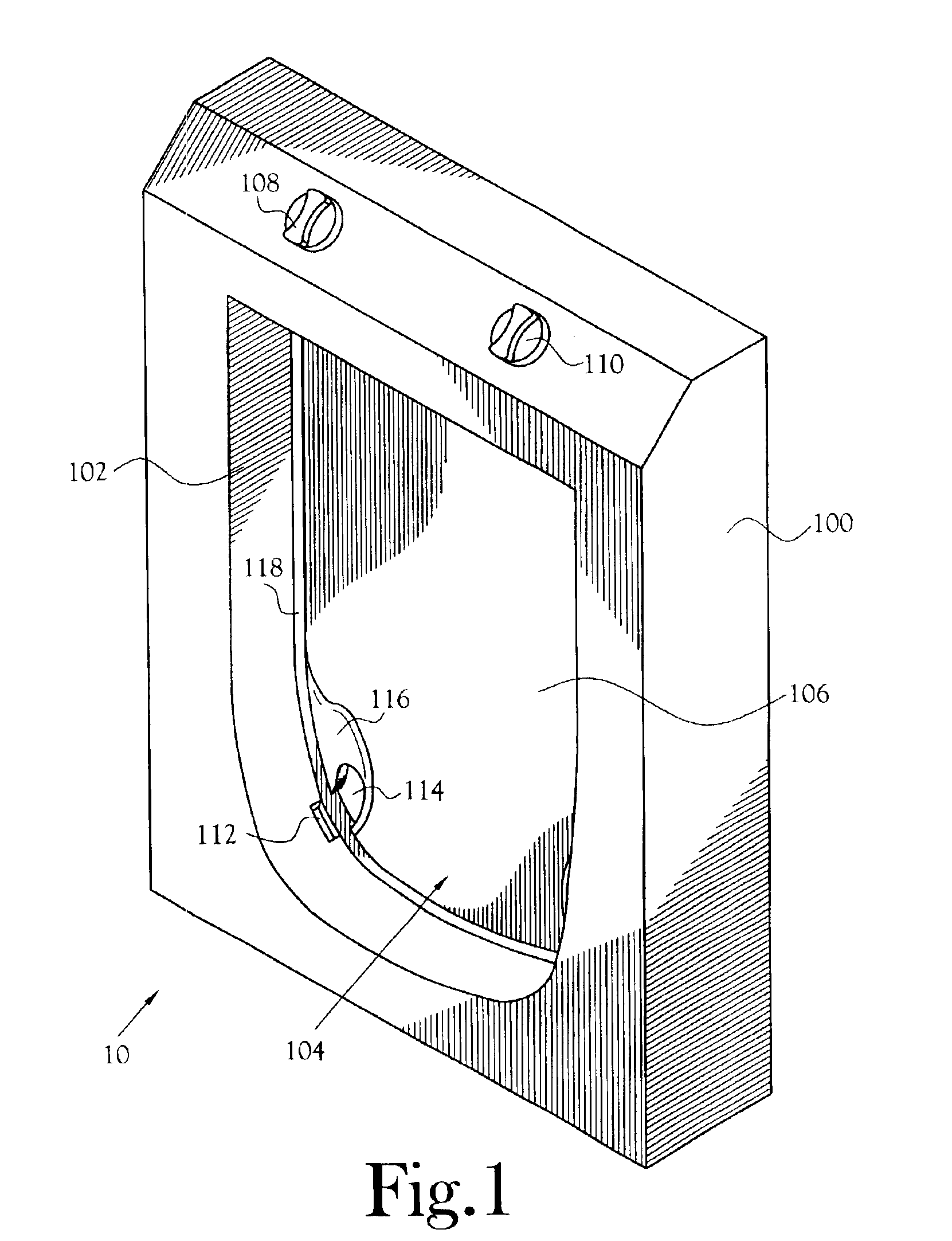
[0025]A pet door according to the present invention is shown and described generally at 10 in the figures. The pet door 10 provides offers ingress or egress through a structural member, such as a wall, a door, or other element commonly used in construction, to a pet. A lock mechanism in the pet door 10 allows the pet owner to restrict ingress and / or egress as desired. The pet door 10 features a dual control system that simplifies the setting of the lock. Each control corresponds to movement of the flap in one direction. The dual control system is also designed to be easier to access than conventional pet door lock mechanism. Further, the dual control system is designed to be less susceptible to unintentional adjustment resulting from incidental contact with the controls.

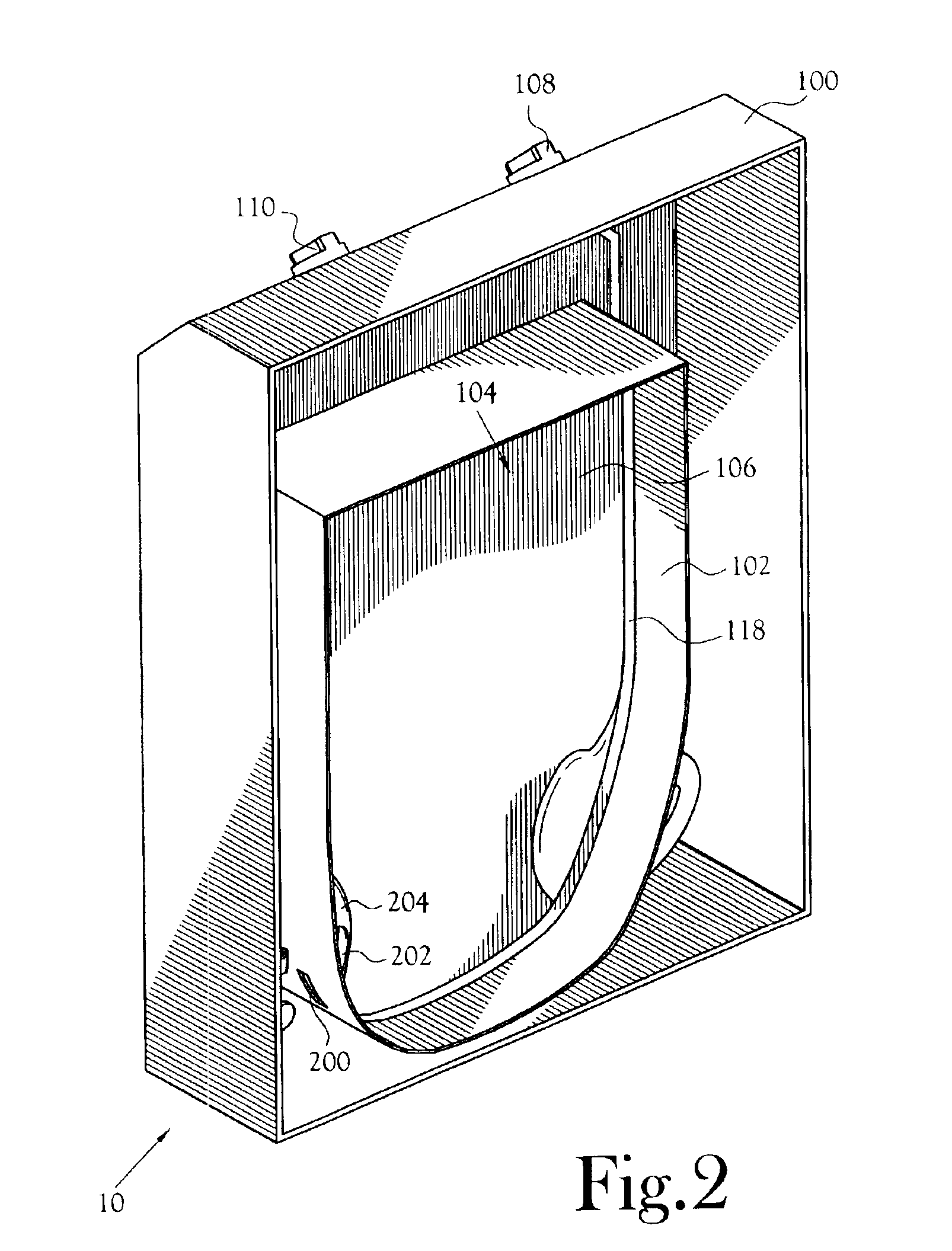
[0026]FIG. 1 illustrates the normally visible face of the pet door 10 when the pet door is installed. FIG. 2 illustrates a face of the pet door 10 that is concealed from view when the pet door is installed. The pet d...


PUM


Abstract

A pet door offering ingress or egress through a structural member. A lock mechanism in the pet door allows the pet owner to restrict ingress and/or egress as desired. The pet door features a dual control system that simplifies the setting of the lock. Each control corresponds to movement of the flap in one direction. The dual control system is also designed to be easier to access than a conventional pet door lock mechanism and to be less susceptible to unintentional adjustment resulting from incidental contact with the controls.

Description

CROSS-REFERENCE TO RELATED APPLICATIONS[0001]Not Applicable.STATEMENT REGARDING FEDERALLY SPONSORED RESEARCH OR DEVELOPMENT[0002]Not Applicable.BACKGROUND OF THE INVENTION[0003]1. Field of Invention[0004]This invention pertains to a lockable pet door. More particularly, this invention pertains to a pet door having a lock mechanism to restrict ingress and egress through the pet door as desired by the pet owner.[0005]2. Description of the Related Art[0006]A pet door allows a pet to independently enter and exit a structure. A standard pet door is installed in an opening cut into a structural member, such as a door or wall. It is desirable for a pet door to provide the owner the ability to restrict ingress and / or egress.[0007]Various lock mechanisms have been utilized to secure a pet door. For example, one commonly used locking mechanism involves lock control, typically a knob or slide, located below the pet door opening which moves a series of tabs into engagement with a flap to block ...

Claims


Application Information

Patent Timeline
Patent Type & Authority Patents(United States)
IPC IPC(8): E06B7/00E06B7/32
CPCE06B7/32
Inventor JOHNSON, RYAN E.STEINBACHER, KURT J.GROH, WILLIAM S.
Owner RADIO SYST CORP
Why Eureka
Try Eureka