Precision guidang device in a machine for machining cylindrical components

Inactive Publication Date: 2010-09-30
ROLLOMATIC
View PDF15 Cites 0 Cited by
  • Summary
  • Abstract
  • Description
  • Claims
  • Application Information

AI Technical Summary

Benefits of technology

[0003]The aim of the present invention is to eliminate this defect by creating a guidance device that retains the components in the machining machine with maximum precision for all the component diameters and which eliminates tedious adjustments

Problems solved by technology

This adjustment work for the position of the vee, according to a minimum of three degrees of freedom, is time consuming, thereby reducing the p

Method used


Image

  • Precision guidang device in a machine for machining cylindrical components
  • Precision guidang device in a machine for machining cylindrical components
  • Precision guidang device in a machine for machining cylindrical components

Examples


Embodiment Construction

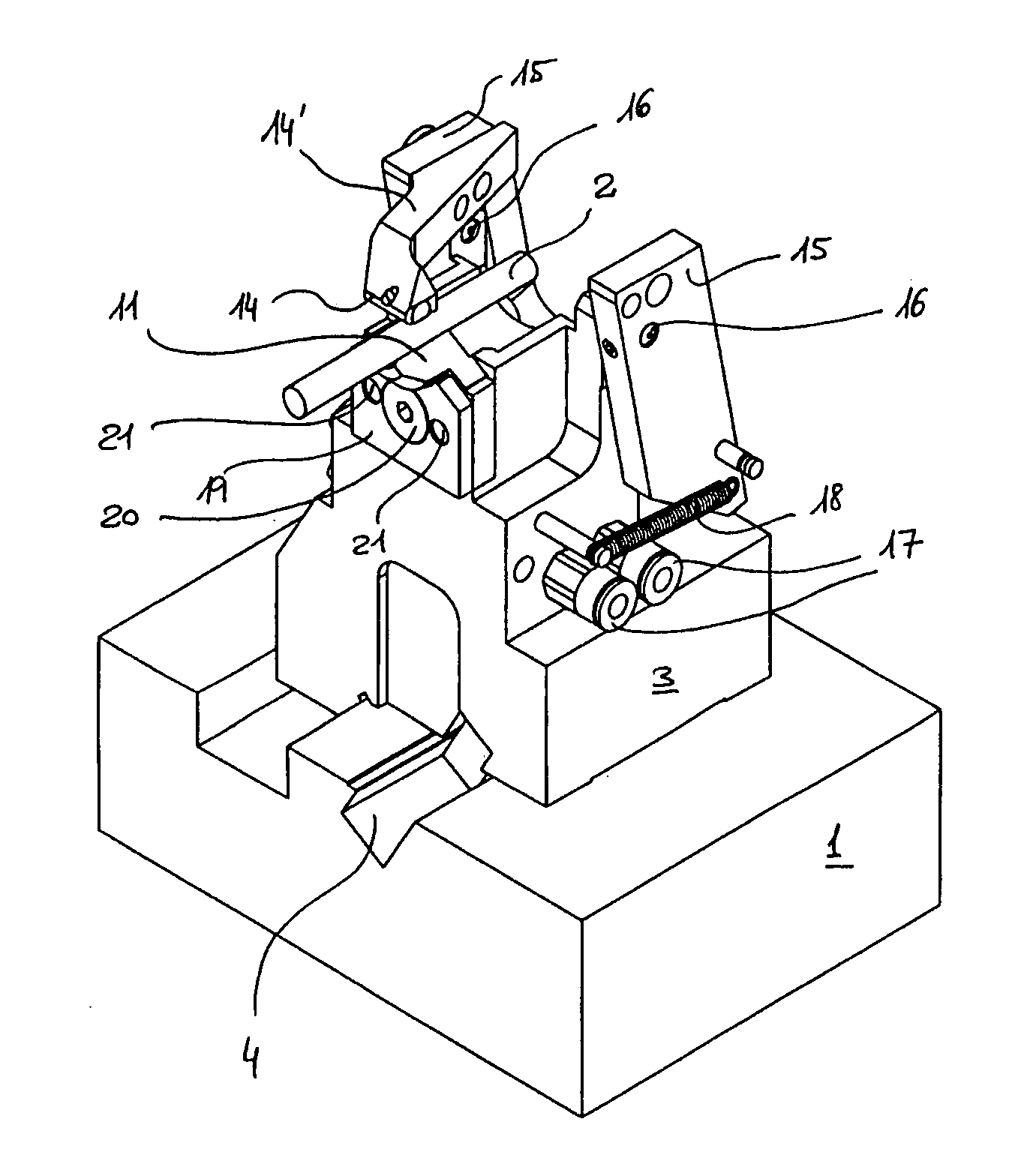
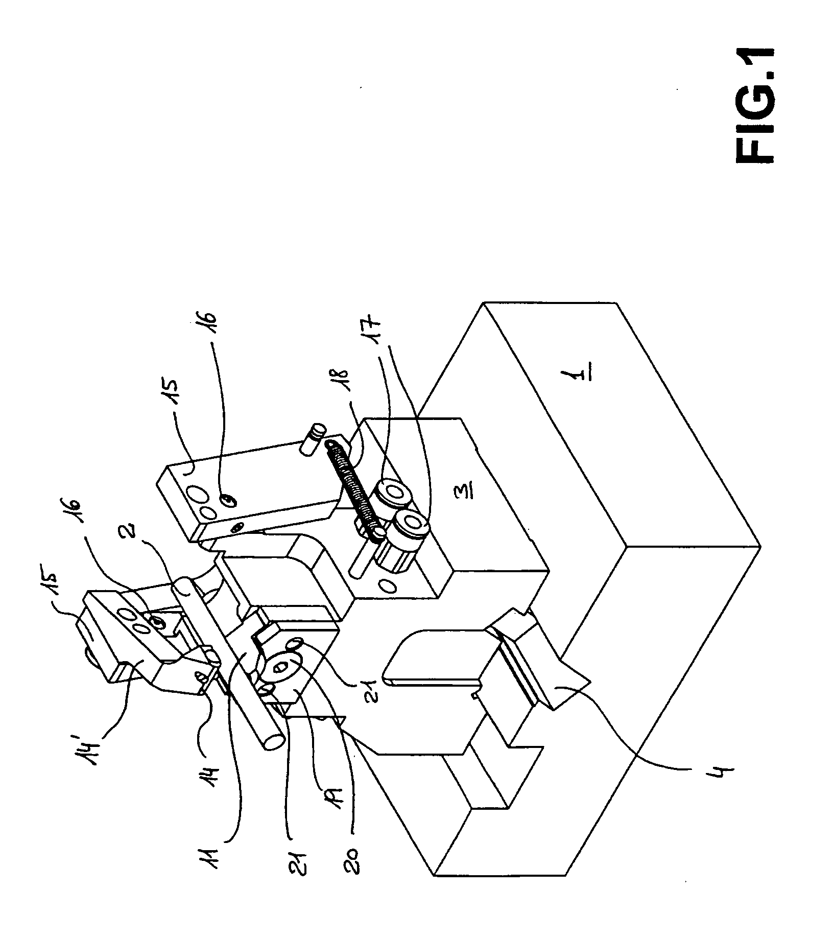
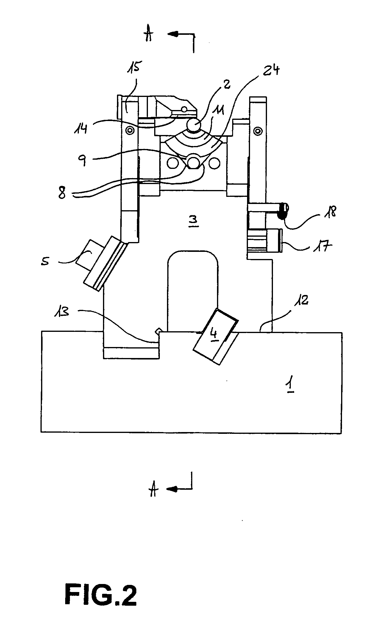
[0013]The guidance device represented in the drawing forms part of a machining machine for manufacturing cylindrical components such as drills made of hard material, the profile of which must be milled or rectified with utmost precision. It comprises a support assembly (FIGS. 1 and 2) mounted on a machine base 1. The support assembly in FIGS. 1 and 2 is arranged in order to maintain according to a strictly determined axis components 2 to be machined, i.e. drilling tools as mentioned above. It comprises a seat 3 fixed on the machine base 1 by a tightening strip 4 and a locking screw 5. For this purpose, the base 1 presents two flat surfaces 12 and 13 (FIG. 2), which are strictly even and perpendicular, against which two corresponding flat faces machined in the lower section of the seat 3 are applied. The seat 3 furthermore presents at its upper front part a machined housing with two oblique and symmetrical flat sides 8 (FIG. 2) and a vertical base which is also flat 9. These surfaces...


PUM


Abstract

The part to be machined (2) is attached so that its axis lies in a position exactly determined relative to the base of the machine (1) and to the pedestal (3) due to the flanges (8) and the rear face (9) of the V formed on the pedestal, and due to an intermediate member (11) having the shape of a crown sector in which the concave cylindrical faces (23) are adapted to the part (2). The part is pressed against the faces (23) by a lug (14) actuated by the calliper (15). The part (2) can be rotated by a floating pin actuated by a servomotor in a determined position relative to the base of the machine (1).

Description

TECHNICAL FIELD[0001]Machining of certain cylindrical tools made of hard materials, such as more or less long small diameter drills, must often fulfil extremely high demands for precision. Now, this is an area of the technology which is progressing towards a reduction in the numbers of components in the series, which raises the problem of a reduction in the unproductive times resulting from adaptation of the tooling to the changes of series. This adaptation must obviously be performed while guaranteeing the utmost quality of the positioning and guiding of the machined components at each modification of the guidance device.BACKGROUND OF THE INVENTION[0002]In conventional machines, the guidance device generally comprises a fixed part with two vee-shaped flat sides in which the component to be machined is engaged and guided and a mobile part, the support finger, which presses the component into the vee while ensuring rotation, the quality of which only depends at that point on the circ...

Claims


Application Information

Patent Timeline
IPC IPC(8): B24B49/00B24B41/06
CPCB24B3/247B24B41/066B24B41/061
Inventor PIGUET, PIERRE-LOUISPAHUD, PIERRE
Owner ROLLOMATIC
Why Eureka
Try Eureka