
Controller for work implement of construction machinery, method for controlling construction machinery, and program allowing computer to execute this method

一种建设机械、控制装置的技术,应用在建设机械的作业机的控制装置、建设机械的控制、以及在计算机中执行该的程序领域,能够解决难以可靠地抑制振动等问题

Inactive Publication Date: 2005-08-17
KOMATSU LTD
View PDF5 Cites 25 Cited by
  • Summary
  • Abstract
  • Description
  • Claims
  • Application Information

AI Technical Summary

Problems solved by technology

[0018] Therefore, since the flow rate of the hydraulic oil becomes zero and the working machine is stopped after a predetermined time elapses from the operation timing of the working machine control lever, there is also a problem of a stop delay.
[0019] In addition, according to Document 5, which discloses the technique of lateral swing welding by a welding robot, since the amplitude of the command input to the control device is limited to a sine wave, when the waveform of the input command signal varies depending on the sequence of operations of the control levers of the working machine, When completely different, it is difficult to reliably suppress vibration even if this technology is directly applied

Method used


Image

  • Controller for work implement of construction machinery, method for controlling construction machinery, and program allowing computer to execute this method
  • Controller for work implement of construction machinery, method for controlling construction machinery, and program allowing computer to execute this method
  • Controller for work implement of construction machinery, method for controlling construction machinery, and program allowing computer to execute this method

Examples


Embodiment approach 1

[0049] (1) Overall composition

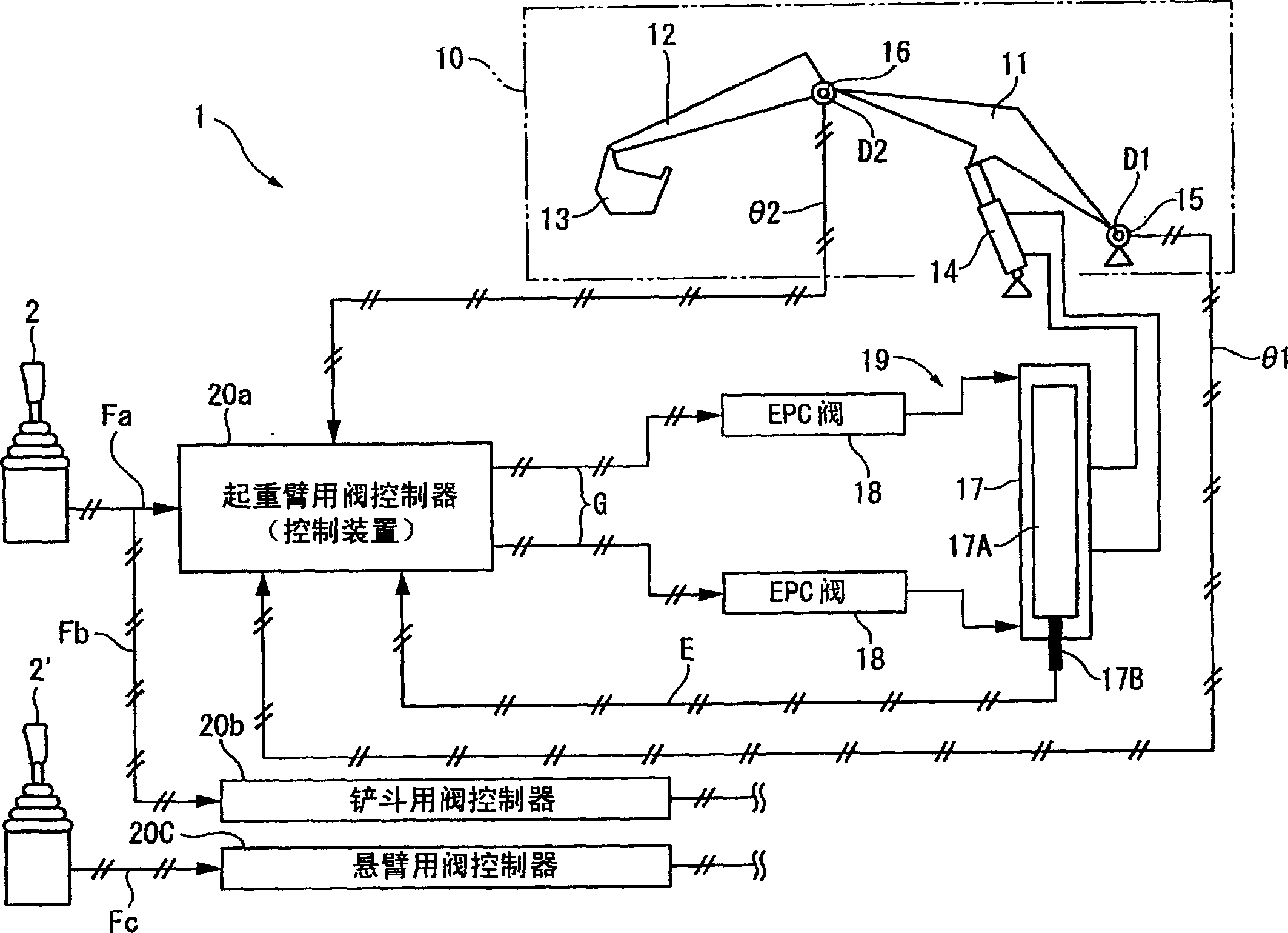
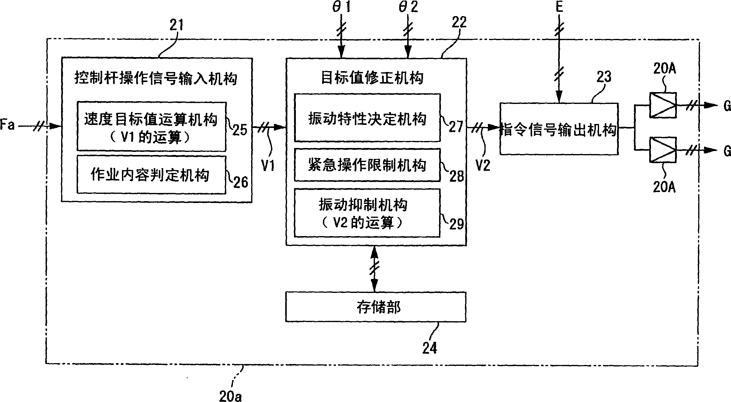
[0050] figure 1 It is a schematic diagram showing a hydraulic excavator (construction machine) 1 equipped with a working machine and a control device thereof according to an embodiment of the present invention. figure 2 is a block diagram showing the controller.

[0051] figure 1 Among them, a hydraulic excavator 1 includes a boom 11 operated by a work machine control lever 2 and a boom 12 operated by a work machine control lever 2', and a bucket 13 is attached to the tip of the boom 12.

[0052] The boom 11 is pivoted around a support point D1 by a hydraulic cylinder 14 .

[0053] The boom 12 rotates around the support point D2 by means of the hydraulic cylinder on the boom 11 . In addition, the bucket 13 is rotated by the hydraulic cylinder on the boom 12 by operating the working machine control lever 2 in the other direction. In addition, the working machine 10 of the present invention is constituted by these boom 11 , boom 12 , and bu...

Embodiment approach

[0163] According to this embodiment, there are the following effects.

[0164] That is, according to the valve controller 20a mounted on the hydraulic excavator 1, since the target value correction mechanism 22 includes the vibration suppressing mechanism 29, the speed target value V1 obtained from the lever operation signal Fa can be corrected to have The speed target value V2 of the inverse characteristic of the predicted vibration of the arm 11 . Therefore, when the actuator 19 is driven by the command signal G generated based on the speed target value V2, the boom 11 can use its own vibration characteristics to eliminate vibration, so that the boom 11 can be adjusted to the speed target value before correction. Like V1, it moves smoothly without swinging.

[0165] At this time, since the speed target value V1 is corrected so as to eliminate the vibration, the principle of vibration suppression is completely different from the conventional case in which the speed change of...

Embodiment approach 2

[0177] Next, Embodiment 2 of the present invention will be described. In addition, in the following description, the same reference numerals are used for the same parts as those already described, and the description thereof will be omitted or simplified.

[0178] The above-described first embodiment is a case where the present invention is applied to a hydraulic excavator 1. The joint angles θ1 and θ2 of the boom 11 and the boom 12 are detected, and the frequency ω and attenuation are obtained from the detected joint angles θ1 and θ2. Based on this rate ξ, the speed target value V2 is corrected.

[0179] In contrast, Embodiment 2 such as Figure 10 As shown, the present invention is applied to the wheel loader 3, and the joint angle θ of the boom 31 of the working machine 30 constituting the wheel loader 3 and the hydraulic cylinder that moves the boom 31 up and down are detected. The oil pressure P of 33 is different in that the correction calculation of the speed target v...


PUM


Abstract

A controller for a work implement (10, 30) of a construction machine (1, 3) comprising: a manipulating signal input unit (21) including a target value computing section (25) for generating an operation target value (V1) for the work implement (10, 30) based on a manipulating signal (F, Fa) inputted from a manipulating unit (2) for manipulating the work implement (10, 30), a target value correcting unit (22, 37) for correcting the generated operation target value (V1), and an instruction signal output unit (23) for outputting an instruction signal to an actuator (19, 34) for driving the work implement (10, 30) according to the corrected target value (V2); wherein the target value correcting unit (22, 37) comprises a vibration suppressing unit (29) for correcting the operation target value (V1) to another target value to suppress vibrations of the construction machine (1, 3) according to the vibration characteristics, which vary according to a posture of and / or a load to the work implement (10, 30).

Description

technical field [0001] The present invention relates to a control device for a working machine of a construction machine, a control method for the construction machine, and a program for executing the method in a computer. Background technique [0002] For example, in construction machinery such as a hydraulic excavator, various operations are performed by operating a work machine composed of a boom and a boom. There is a problem of wobbling in the working machine. [0003] This phenomenon is caused by the momentary stop or momentary start of the supply of hydraulic oil to the actuator when the working machine is operated by an actuator including a hydraulic cylinder, and it is caused by the inability to smoothly absorb the hydraulic oil that is being operated. It is caused by the inertial force of the machine or the work machine that has stopped. [0004] In addition, when swinging occurs in a work machine with a large inertia such as a boom or a boom, since the entire hy...

Claims


Application Information

Patent Timeline
Patent Type & Authority Applications(China)
IPC IPC(8): E02F9/22E02F3/43E02F9/20G05B13/00G05B19/00
CPCE02F9/2207F16L1/24F16L9/12
Inventor 冈村健治野濑松男木村洋一朗
Owner KOMATSU LTD
Learn More