
Lifting control method, device and system as well as lifting appliance and hoisting machine

A control algorithm and spreader technology, applied in the field of hoisting control of hoisting machinery and spreaders, can solve problems such as unsatisfactory, and achieve the effects of suppressing swing, improving anti-sway effect and improving anti-sway ability.

Active Publication Date: 2013-03-20
ZOOMLION HEAVY IND CO LTD
View PDF5 Cites 25 Cited by
  • Summary
  • Abstract
  • Description
  • Claims
  • Application Information

AI Technical Summary

Problems solved by technology

However, this kind of spreader is significantly affected by factors such as the weight of the hoist, the length of the wire rope, and external disturbances, and the effect of suppressing the sway of the hoist is not ideal.

Method used


Image

  • Lifting control method, device and system as well as lifting appliance and hoisting machine
  • Lifting control method, device and system as well as lifting appliance and hoisting machine
  • Lifting control method, device and system as well as lifting appliance and hoisting machine

Examples


no. 1 example

[0062] Such as Figure 6 As shown, the first embodiment of the hoisting control method of the hoisting machinery of the present invention, using the spreader described in the previous embodiment, includes the following steps:

[0063] Step 101. Obtain the swing angle information of the suspension beam detected by the first detection device relative to the spreader frame in the vertical plane, the posture displacement information of the spreader frame relative to the inertial coordinate system detected by the second detection device, and the third detection device The attitude displacement information of the delivery platform detected by the device relative to the inertial coordinate system;

[0064] Step 102: output the first swing control signal according to the swing angle information of the hanging beam, the attitude displacement information of the spreader frame, the attitude displacement information of the delivery platform and the first swing control algorithm, and contr...

no. 3 example

[0071] The third embodiment of the hoisting control method of the present invention further includes:

[0072] Obtain the rotation angle information of the gear turntable detected by the fifth detection device;

[0073] According to the rotation angle information of the gear turntable, the attitude displacement information of the spreader frame, the attitude displacement information of the delivery platform and the third swing control algorithm, the third swing control signal is output to control the rotation of the gear turntable relative to the pallet to the lifting beam and the delivery platform counterpoint.

[0074] The method in this embodiment is applicable to the situation where the hoisting weight and the loading platform are not aligned. The delivery area of ​​the cargo platform. The third swing control signal is used to control the gear turntable of the turntable to rotate relative to the pallet until the lifting beam is aligned with the loading platform. This emb...


PUM


Abstract

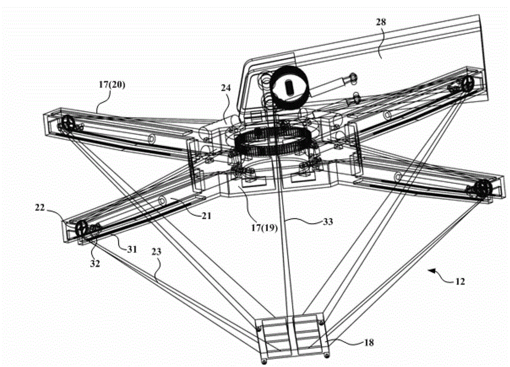
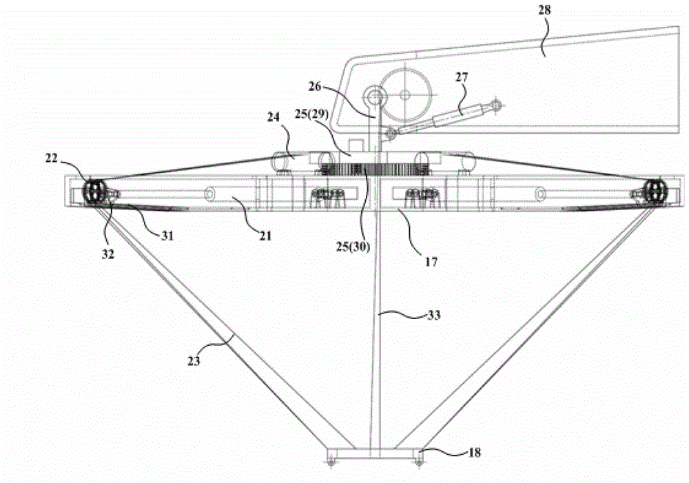
The invention relates to the technical field of engineering machinery, and discloses lifting control method, device and system as well as a lifting appliance and a hoisting machine, and is used for effectively restraining the swing of a lifting weight in the lifting process. The lifting appliance comprises a lifting appliance frame and a lifting beam, wherein the lifting appliance frame comprises a box type frame body and at least three arm type frame bodies extending from the box type frame body in a radiating way, and the lifting beam is positioned below the box type frame body; the lifting appliance further comprises a first telescopic device, a pulley and at least one anti-swing steel wire rope, wherein the first telescopic device is correspondingly arranged on each arm type frame body; the pulley is fixedly connected with one end of the first telescopic device; and one end of the at least one anti-swing steel wire rope is coiled in an anti-swing steel wire rope reel fixed on the box type frame body, and the other end of the at least one anti-swing steel wire rope is connected with the lifting beam after bypassing the pulley.

Description

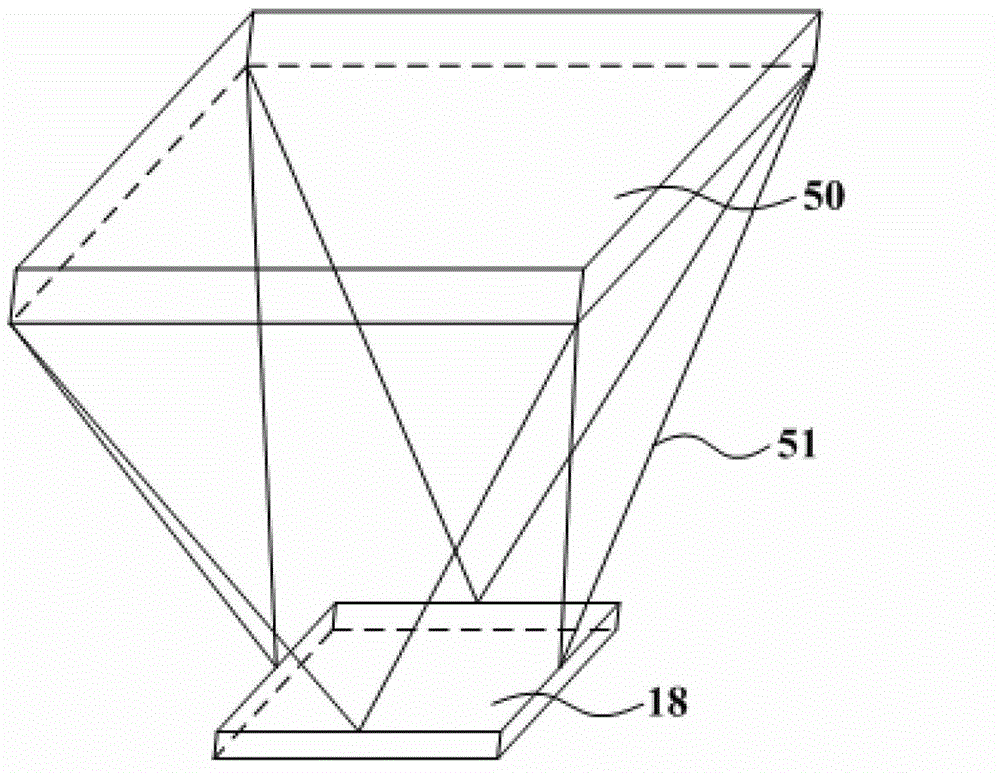
technical field [0001] The invention relates to the technical field of hoisting machinery, in particular to a hoisting control method, device and system of a hoisting machinery, a spreader, and a hoisting machinery. Background technique [0002] For hoisting machinery, such as large-scale offshore platform hoisting machinery or port hoisting machinery, etc., during the hoisting process of containers, etc., due to the interference of wind and waves, the rotation and pitching of the jib, the hoisting often occurs Big swing. When the swing range of the hoisting weight is large, on the one hand, it is not conducive to the rapid and stable completion of the hoisting task, affecting work efficiency; Heavy quality, but also increased safety hazards. [0003] Such as figure 1 As shown, an existing anti-sway sling is connected between the trolley 50 and the suspension beam 18 by four groups of steel wire ropes 51 that are inverted. The use of steel wire rope cable pull can change...

Claims


Application Information

Patent Timeline
Patent Type & Authority Applications(China)
IPC IPC(8): B66C1/12B66C13/18
Inventor 高常春任会礼
Owner ZOOMLION HEAVY IND CO LTD
Learn More