

Short circuit simulation test circuit and test method thereof
A technology for simulating tests and circuits, applied in the direction of measuring electricity, measuring electrical variables, measuring devices, etc., can solve the problems of long action time, high voltage, large current, etc., and achieve the effect of favorable safety, convenient implementation and simple control.
Inactive Publication Date: 2015-03-18
NR ELECTRIC CO LTD +1
View PDF6 Cites 348 Cited by
- Summary
- Abstract
- Description
- Claims
- Application Information
AI Technical Summary
Problems solved by technology
The system voltage is high, the current is large, and the capacity is large. It is difficult to build a full-load circuit in the test environment that is the same as the actual operating condition for testing. Therefore, how to build an equivalent test circuit in the test environment to test the strength of the actual operating Quite experimentation becomes the key to solving the problem
[0003] In the actual operation of high-power power electronic devices based on turn-off device valves,
Method used
View moreImage
Smart ImageViewing Examples

Examples
 PUM
 Abstract
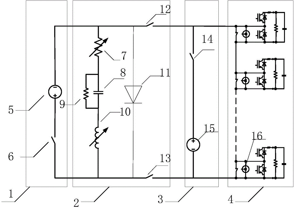
The invention discloses a short circuit simulation test circuit which is used for testing and examining the operation condition of a converter valve. The short circuit simulation test circuit comprises a capacity charge power supply module, a fault current generation circuit and a converter valve charging source module, wherein the cathode of the capacity charge power supply module is connected with a positive input end of the fault current generation circuit while the anode of the capacity charge power supply module is connected with a negative input end of the fault current generation circuit; a positive input end of the fault current generation circuit is connected with the anode of the converter valve charging source module and a high voltage output end of the converter valve respectively, and the negative output end of the fault current generation circuit is connected with the cathode of the capacity charge power supply module and the low voltage output end of the converter valve respectively. The test circuit can be used for testing and examining the fault operation condition of converter value. The invention further discloses a test method of the short circuit simulation test circuit.
Description
technical field [0001] The invention relates to an operation test method of high-power electric electronic technology, in particular to a short-circuit simulation test circuit and a test method. Background technique [0002] With the application of high-power power electronic converter technology in the power system, the reliability of its core component, the converter valve, becomes the key to system safety. The system voltage is high, the current is large, and the capacity is large. It is difficult to build a full-load circuit in the test environment that is the same as the actual operating condition for testing. Therefore, how to build an equivalent test circuit in the test environment to test the strength of the actual operating Quite experimentation becomes the key to solving the problem. [0003] In the actual operation of high-power power electronic devices based on turn-off device valves, the anti-parallel diode overcurrent of the insulated gate bipolar transistor (...
Claims
Login to View More Application Information
Patent Timeline
 IPC IPC(8): G01R31/02
Inventor连建阳姜田贵朱铭炼谢晔源段军殷冠贤
OwnerNR ELECTRIC CO LTD