Automatic optical fiber transmission delay locking and equalization method

A technology of equalization compensation and automatic locking, which is applied in the direction of transmission system, digital transmission system, transmission monitoring/testing/fault measurement system, etc. Stability and other issues, to achieve the effect of filtering out drift, filtering out jitter noise, and filtering out cumulative drift

Active Publication Date: 2015-03-18
四川泰富地面北斗科技股份有限公司
View PDF6 Cites 8 Cited by
  • Summary
  • Abstract
  • Description
  • Claims
  • Application Information

AI Technical Summary

Problems solved by technology

[0009] The purpose of the present invention is to overcome the fact that the existing technology cannot eliminate the extremely slow delay drift and drift accumulation caused by the extremely slow change of the optical fiber transmission delay with time, temperature, fiber aging, etc., which will bring adverse effects on time and frequency synchronization , resulting in shortcomings such as optical transmission network instability, communication failure alarms, etc.
Compared with the existing inventions "a method for automatic equalization and compensation of time delay asymmetry difference" and "a method for accurate measurement of time delay asymmetry difference", the present invention solves the daily fluctuation of optical fiber time delay with temperature changes , monthly fluctuations, annual fluctuations, and the extremely slow delay drift and drift accumulation introduced by fiber aging drift, not only improve the measurement accuracy of fiber delay ≤ (1ns / day ~ 2ns / day ~ 5ns / day ~ 10ns / day ), and can realize automatic locking and equalization compensation for slow changes in fiber transmission delay

Method used


Image

  • Automatic optical fiber transmission delay locking and equalization method
  • Automatic optical fiber transmission delay locking and equalization method
  • Automatic optical fiber transmission delay locking and equalization method

Examples


Embodiment

[0035] In order to make the technical means, creative features, goals and effects achieved by the present invention easy to understand, the present invention will be further described below in conjunction with specific illustrations.

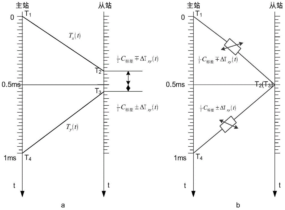
[0036] see figure 1 , the optical fiber transmission delay automatic locking and equalization compensation method involved in the present invention, under the existing SDH system of optical fiber transmission system, based on the online monitoring technology of optical fiber delay, a zero-attenuation programmable optical fiber delay equalization compensation network is added at the slave station , choose C corresponding to the fiber transmission delay between master and slave stations 标 And its corresponding time interval code Txk for round-trip comparison of time, using the three-point normalization accurate measurement algorithm, can complete the automatic locking and equalization compensation of the optical fiber transmission delay.

[0037]...


PUM


Abstract

The invention discloses an automatic optical fiber transmission delay locking and equalization method applicable to optical fiber communication networks. Under the SDH (Synchronous Digital Hierarchy) system of conventional optical fiber transmission devices, by adding a zero-attenuation program-controllable optical fiber delay equalization network, in combination with an on-line optical fiber delay monitoring technique, the method reasonably chooses C mark and a time interval code Txk corresponding to C mark, a round trip comparison phase locking technique is utilized to separate out the change of an optical fiber delay value between a master station and a slave station in order to eliminate the adverse affection of the change of the optical fiber delay value on time and frequency synchronization, a three point-to-one point accurate measurement algorithm is adopted to constantly control the change of the optical fiber delay within an extremely narrow range, and thereby high-precision time and frequency synchronization is realized. The method provided by the invention is applied in combination with the on-line optical fiber delay monitoring technique, and can firmly control the delay change of optical fiber transmission within a range less than or equal to (1ns/day to 2ns/day to 5ns/day to 10ns/day).

Description

technical field [0001] The invention belongs to the technical field of optical fiber communication, and relates to a method for automatic locking and equalization compensation of optical fiber time delay in an optical fiber transmission network. Background technique [0002] With the development of optical communication transmission technology, extremely precise time-frequency synchronization technology (≤1ns, ≤1E-13 / day, which is 100 times higher than the existing time-frequency accuracy) has become a major topic of time-frequency research worldwide. However, the currently operating time-frequency synchronization network is difficult to implement because the time-frequency signal is greatly damaged during the transmission process of the optical fiber communication network. Aiming at the problem of precise measurement of optical fiber delay, domestic scholars have proposed some useful methods, and some have applied for related invention patents, such as: [0003] 1. Inventi...

Claims


Application Information

Patent Timeline
Patent Type & Authority Applications(China)
IPC IPC(8): H04B10/07H04L7/033H04J3/14
Inventor 孟志才李忠文李高峰李有生李琦彭良福
Owner 四川泰富地面北斗科技股份有限公司
Why Eureka
Try Eureka