Image processing device and image processing method
An image processing device and image processing technology, applied in image data processing, image enhancement, image analysis, etc., can solve the problems of fewer images, increased processing time, and the inability to obtain the number of composites, etc.
- Summary
- Abstract
- Description
- Claims
- Application Information
AI Technical Summary
Problems solved by technology
Method used
Image

Examples
no. 1 approach
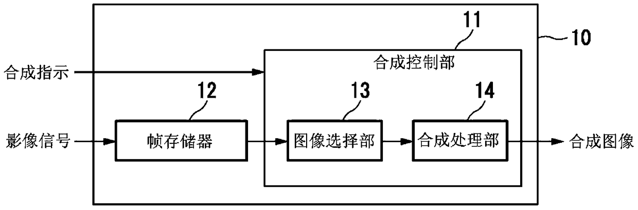
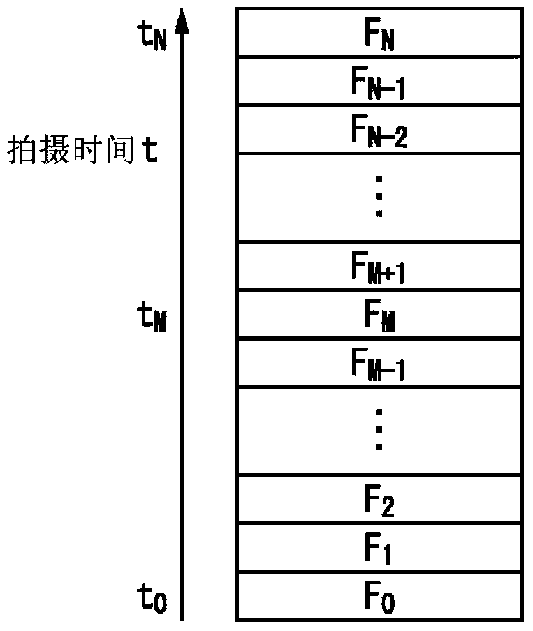
[0055] Hereinafter, a first embodiment of the present invention will be described with reference to the drawings. figure 1 It is a block diagram showing the configuration of the image processing device 10 in this embodiment. exist figure 1 Among them, the image processing device 10 includes a composition control unit 11 and a frame memory (memory) 12 . The synthesis control unit 11 includes an image selection unit 13 and a synthesis processing unit 14 , and generates a synthesized image. The frame memory 12 stores input video signals (a plurality of captured images). The video signal is, for example, a moving image and includes frames obtained by continuous shooting.
[0056] When a compositing instruction is input, the image selection unit 13 selects a reference image to be composited and a plurality of composite target images to be composited with the reference image from among the frames included in the video signal stored in the frame memory 12 . The synthesis processi...
no. 2 approach
[0086] Next, a second embodiment of the present invention will be described with reference to the drawings. In the present embodiment, the reference image is selected based on the amount of motion of the subject estimated by the motion amount estimating unit 21 described later.
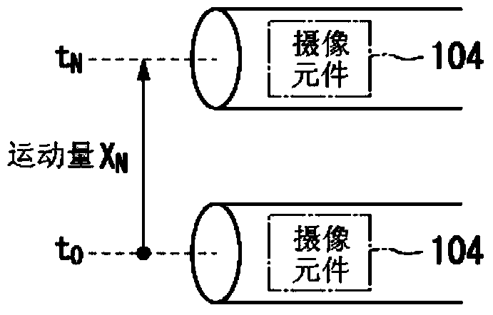
[0087] Figure 8 It is a block diagram showing the configuration of the image processing device 20 in this embodiment. exist Figure 8 Among them, the image processing device 20 includes a composition control unit 11 , a frame memory 12 , and a motion amount estimation unit 21 . The composition control unit 11 and the frame memory 12 are the same as those in the first embodiment. The exercise amount estimation unit 21 estimates the exercise amount X of the subject. In addition, there are several methods of estimating the amount of motion of a subject. For example, the following methods are considered: estimating the motion amount of the subject within a newly input frame by comparing the luminanc...
no. 3 approach
[0119] Next, a third embodiment of the present invention will be described with reference to the drawings. In this embodiment, the required minimum number of the total of the reference image and the image to be synthesized (hereinafter referred to as the required number of synthesized images) is set according to the amount of noise included in each frame.
[0120] Figure 14 It is a block diagram showing the configuration of the image processing device 30 in this embodiment. In the illustrated example, the image processing device 30 includes a composition control unit 11 , a frame memory 12 , and a noise amount estimation unit 31 . The composition control unit 11 and the frame memory 12 are the same as those in the second embodiment.
[0121] The noise amount estimating section 31 estimates the noise amount of a frame. As a method of estimating the amount of noise, for example, it is estimated from a gain value. The noise amount estimating unit 31 uses a gain value determi...
PUM
 Abstract
Description
Claims
Application Information
 - R&D
- Intellectual Property
- Life Sciences
- Materials
- Tech Scout
- Unparalleled Data Quality
- Higher Quality Content
- 60% Fewer Hallucinations
Browse by: Latest US Patents, China's latest patents, Technical Efficacy Thesaurus, Application Domain, Technology Topic, Popular Technical Reports.
© 2025 PatSnap. All rights reserved.Legal|Privacy policy|Modern Slavery Act Transparency Statement|Sitemap|About US| Contact US: help@patsnap.com