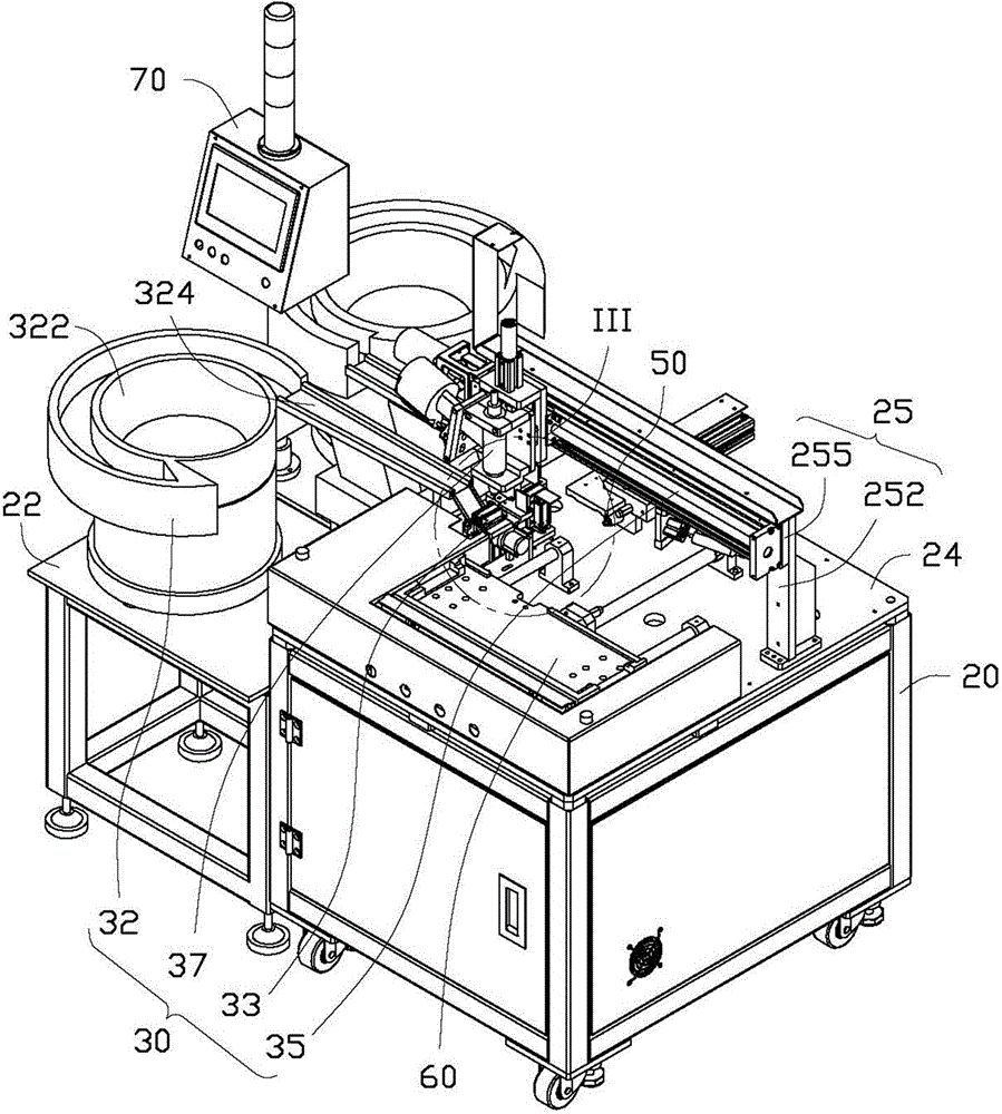
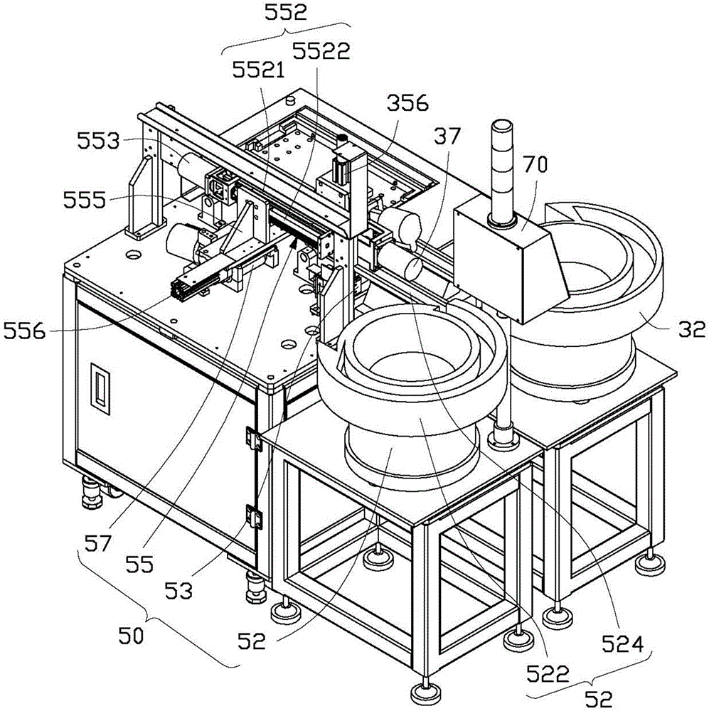
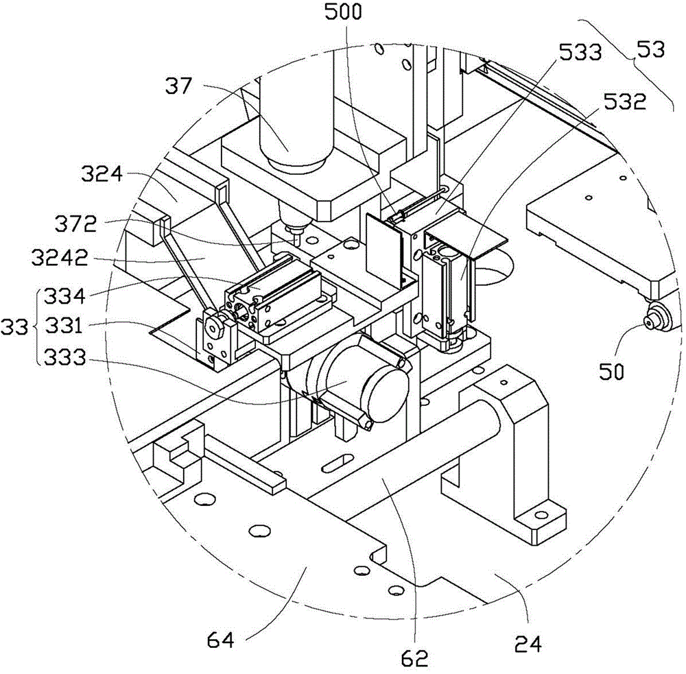
[0073] Please refer to figure 1 and 2 , The preferred embodiment of the automatic riveting device of the present invention is used to rivet 500 (such as image 3 and Figure 4 Shown) Automatic feeding, distributing and positioning and riveting to blank 300 (such as Figure 7 Shown). The automatic riveting device includes a bracket 20, a vertical riveting assembly 30, a horizontal riveting assembly 50, a tray 60, and a control assembly 70.
[0074] The bracket 20 is provided with a first supporting plate 22 and a second supporting plate 24 on one side of the first supporting plate 22. The second supporting plate 24 is higher than the first supporting plate 22. The second support plate 24 is provided with a mounting frame 25, and the mounting frame 25 includes two opposite fixing posts 252 fixed on both sides of the second support plate 24 and a support plate 255 connected to the top ends of the two fixing posts 252. The vertical riveting assembly 30, the horizontal riveting assembly 50, the tray 60 and the control assembly 70 are all installed on the first support plate 22 and the second support plate 24.
[0075] The vertical riveting assembly 30 includes a first feeding mechanism 32 fixed to the front end of the first supporting plate 22, a first distributing mechanism 33 fixed to the second supporting plate 24 adjacent to the first feeding mechanism 32, a The first driving mechanism 35 and a first rivet gun 37 are fixed on the front side of the supporting plate 255 of the mounting frame 25.
[0076] In this embodiment, the first feeding mechanism 32 is a vibrating plate, and the first feeding mechanism 32 includes a vibrating part 322 and a feeding trough 324 connected to the vibrating part 322. The feeding trough 324 is provided with a distributing structure (not shown in the figure) for moving the rivet 500 in a set direction. The discharge port of the conveying trough 324 is provided with a hopper 3242 extending to the first distributing mechanism 33 (such as image 3 Shown).
[0077] Please refer to Figure 3 to Figure 6 , The first distributing mechanism 33 includes a mounting frame 331 fixed to the second support plate 24, a turning member 332 arranged on the side of the mounting bracket 331 adjacent to the hopper 3242, and a turning member 332 that drives the turning member 332 to turn over. The rotating cylinder 333, a positioning member 334, a pushing cylinder 335 and a number of sensors 337.
[0078] The turning member 332 includes a turning plate 3321, a fixing hook 3322 rotatably installed on the upper end side of the turning plate 3321, and a slidable pusher that is slidably installed on the turning plate 3321 and can resist the rotation of the fixed hook 3322. Rod 3323. An elastic member (shown at the end of the figure) for forcing the fixing hook 3322 to reset is provided between the fixing hook 3322 and the turning plate 3321. The turning board 3321 defines a positioning slot 3325.
[0079] The rotating cylinder 333 is installed on the other side of the mounting frame 331, and the rotating cylinder 333 includes a driving shaft 3331 rotatably passing through the mounting frame 331 and fixed to the middle of the turning plate 3321. The rotating cylinder 333 can drive the turning member 332 to rotate along the drive shaft 3331.
[0080] The positioning member 334 includes a positioning cylinder 3342 fixed to the upper part of the mounting frame 331 and a positioning plate 3343 connected to the positioning cylinder 3342. The positioning plate 3343 is provided with a positioning hook 3345. The positioning cylinder 3342 can drive the positioning plate 3343 to slide to make the positioning hook 3345 move in the horizontal direction.
[0081] The thrust cylinder 335 is fixed to the lower part of the mounting frame 331. The push cylinder 335 is provided with a push rod 3352 which resists the push rod 3323 away from the fixing hook 3322. The push rod 3352 resists the push rod 3323, so that the fixing hook 3322 is away from the turning plate 3321 and opens.
[0082] When the first distributing mechanism 33 is used, the rivet 500 is input into the positioning groove 3325 of the turning plate 3321 from the discharge port of the feeding trough 324 through the hopper 3242. When the sensor 337 senses that the rivet 500 is received in the positioning groove 3325, it sends a signal to the control assembly 70, which controls the pushing cylinder 335 to work so that the push rod 3352 disengages from the push rod 3323. , The fixing hook 3322 is reset and clamped to the rivet 500. The rotating cylinder 333 drives the turning plate 3321 to rotate 90 degrees counterclockwise along the drive shaft 3331 to make the rivet 500 stand upright. The positioning cylinder 3342 drives the positioning plate 3343 to slide, so that the positioning hook 3345 abuts the rivet 500 to maintain the rivet 500 in an upright state so that the first rivet gun 37 can take materials.
[0083] See Figure 7 The first driving mechanism 35 includes a first transmission member 352, a first motor 353, and a first sliding frame 355. The first transmission member 352 includes a fixed frame 3521 fixed on the front side of the supporting plate 255 and a first screw rod 3522 rotatably fixed to the middle of the fixed frame 3521 and extending along the length of the supporting plate 255. The first motor 353 is fixed to one end of the supporting plate 255 and drives the first screw 3522 to rotate. The first sliding frame 355 is slidably installed on the fixed frame 3521 and sleeved on the first screw 3522. A first air cylinder 356 capable of driving the first rivet gun 37 to move up and down is fixed to the first sliding frame 355. The first motor 353 drives the first screw 3522 to rotate so as to drive the first sliding frame 355 to slide left and right along the first screw 3522.
[0084] The first rivet gun 37 is installed on the first sliding frame 355, and the nozzle 372 of the first rivet gun 37 faces the second support plate 24.
[0085] The transverse riveting assembly 50 includes a second feeding mechanism 52 fixed to the rear end of the first supporting plate 22, a second distributing mechanism 53 fixed to the second supporting plate 24 adjacent to the second feeding mechanism 52, and a fixed A second driving mechanism 55 and a second rivet gun 57 are behind the supporting plate 255 of the mounting frame 25.
[0086] In this embodiment, the second feeding mechanism 52 is a vibrating plate, and the second feeding mechanism 52 includes a vibrating portion 522 fixed to the rear end of the first support plate 22 and a feeding trough 524 connected to the vibrating portion 522 . The feeding trough 524 extends to the second distributing mechanism 53.
[0087] See image 3 The second distributing mechanism 53 is facing the discharging port of the conveying trough 524, and a distributing structure is provided in the conveying trough 524 to move the rivet 500 in a set direction. The second distributing mechanism 53 includes a distributing cylinder 532 and a reclaiming block 533 connected to the distributing cylinder 532. The reclaiming block 533 is provided with a structure for positioning the rivet 500. The rivet 500 is input from the discharge port of the feeding trough 524 to the reclaiming block 533 of the second distributing mechanism 53 and positioned, the distributing cylinder 532 drives the reclaiming block 533 to move upward to push the rivet 500 Out. At this time, the rivet 500 maintains a horizontal state.
[0088] See figure 2 The second driving mechanism 55 includes a second transmission element 552, a second motor 553, and a second sliding frame 555. The second transmission member 552 includes a fixed frame 5521 fixed on the rear side of the supporting plate 255 and a second screw rod 5522 rotatably fixed to the middle of the fixed frame 3521 and extending along the length of the supporting plate 255. The second motor 553 is fixed to the other end of the support plate 255 and drives the second screw 5522 to rotate. The second sliding frame 555 is slidably installed on the fixed frame 5521 and sleeved on the second screw 5522. A second air cylinder 556 that drives the second rivet gun 57 to move back and forth is fixed on the second sliding frame 555. The second motor 553 drives the second screw 5522 to rotate so as to drive the second sliding frame 555 to slide left and right along the second screw 5522.
[0089] The second rivet gun 57 is installed on the second sliding frame 555, and the nozzle 572 of the second rivet gun 57 is parallel to the second support plate 24.
[0090] The tray 60 includes two guide posts 62 fixed on the second support plate 24 and extending in the front-rear direction, a carrier plate 64 that is slidably installed on the two guide posts 62 and can slide back and forth along the two guide posts 62, and a carrier plate 64. A third motor 65 drives the carrier plate 64 to slide. The third motor 65 can drive the carrier plate 64 to slide back and forth.
[0091] The control assembly 70 includes a controller 72 and two control buttons 75. The controller 72 is used to control the operations of the first motor 353, the second motor 553, the third motor 65, the rotating cylinder 333, the first cylinder 356, the second cylinder 556, the first rivet gun 37 and the second rivet gun 57.
[0092] Please refer to Figure 7 to Figure 10 When in use, put the rivet 500 into the first and second feeding mechanisms 32, 52, mount the blank 300 on the carrier plate 64, press the control button 75, start the third motor 65 to drive the carrier plate 64 Slide along the two guide posts 62 to below the mounting frame 25. The vibration part 322 of the first feeding mechanism 32 vibrates so that the rivet 500 is transported along the feeding trough 324 through the hopper 3242 to the positioning groove 3325 of the turning piece 332 of the first distributing mechanism 33. After the sensor 337 senses the rivet 500 , Issue a command to the control assembly 70, the control assembly 70 controls the push cylinder 335 to release the push rod 3323, the fixed hook 3322 rotates to reset to position the rivet 500, at the same time, the control assembly 70 controls the rotation The air cylinder 333 is activated to rotate the turning member 332 so that the rivet 500 is in a vertical state and the positioning member 334 positions the rivet 500. The first motor 353 is activated to drive the first screw 3522 to rotate, so that the first sliding frame 355 slides adjacent to the first distributing mechanism 33 until the nozzle 372 of the first rivet gun 37 faces the rivet 500. The first air cylinder 356 drives the first rivet gun 37 to move downward to suck the rivet 500 and reset. The first motor 353 drives the first screw rod 3522 to reverse to drive the first sliding frame 355 to slide, and the rivet 500 on the gun nozzle 372 faces the mounting hole 302 on the top of the blank 300. The first air cylinder 356 drives the first rivet gun 37 to move downward, so that the first rivet gun 37 rivets the rivet 500 into the mounting hole 302. The vibration part 522 of the second feeding mechanism 52 vibrates so that the rivet 500 is transported along the conveying trough 524 to the reclaiming block 533 of the second distributing mechanism 53 and positioned. The distributing cylinder 532 drives the reclaiming block 533 to move upward to move The rivet 500 is ejected. The second motor 553 is activated to drive the second screw rod 5522 to rotate, so that the second sliding frame 555 slides adjacent to the second distributing mechanism 53 until the nozzle 572 of the second rivet gun 57 faces the rivet 500. The second air cylinder 556 drives the second rivet gun 57 to move forward to suck the rivet 500. The second motor 553 drives the second screw rod 5522 to reverse so that the second sliding frame 555 slides away from the second distributing mechanism 53 until the rivet 500 on the gun nozzle 572 is facing the side of the blank 300 Mounting hole 304. The second air cylinder 556 drives the second rivet gun 57 to move forward, so that the second rivet gun 57 rivets the rivet 500 into the mounting hole 304. The third motor 65 drives the carrier plate 64 to slide forward to reset, and then the blank 300 can be taken out.