Unlocking device for container, lock structure with unlocking device and container

A technology for unlocking devices and containers, which is applied in the directions of packaging, transportation, packaging, containers, etc. It can solve problems such as the limitation of unloading methods, the inaccessibility of operators, and the inability to perform remote unloading of boxes, so as to meet the requirements of lowering, The effect of eliminating potential safety hazards

Active Publication Date: 2017-03-22
NANTONG CIMC SPECIAL TRANSPORTATION EQUIP MFR +2
View PDF7 Cites 0 Cited by
  • Summary
  • Abstract
  • Description
  • Claims
  • Application Information

AI Technical Summary

Problems solved by technology

When manually opening the door lock for bulk cargo unloading, there will be certain safety hazards
[0005] Secondly, when the box body needs to be unloaded in the mid-air of hoisting, because the box body is far away from the ground, the operator cannot reach and unlock the box body, and the box body cannot be remotely unloaded.
[0006] Due to the above defects, ordinary bulk containers have more restrictions on the way of unloading

Method used


Image

  • Unlocking device for container, lock structure with unlocking device and container
  • Unlocking device for container, lock structure with unlocking device and container
  • Unlocking device for container, lock structure with unlocking device and container

Examples


no. 1 example

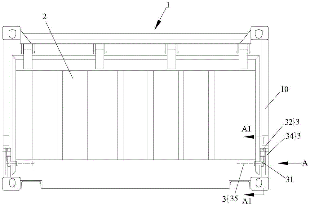
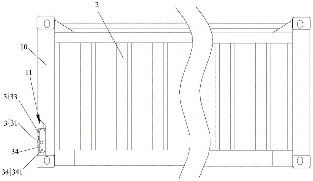
[0041] Figure 1A Shown is a left side view of a container having an unlocking device according to a first embodiment of the present invention. Figure 1B shown as Figure 1A The front view of the container in . Such as Figure 1A and Figure 1B As shown, the container includes a box body 1 and a cargo discharge door 2, and the unlocking device 3 proposed in the first embodiment of the present invention is provided on the left and right corner posts 10 of the box body 1 and the cargo discharge door 2 for connecting the two. The left and right corner posts 10 have gaps 11 for accommodating a part of the unlocking device 3 .

[0042] Figure 1C shown as Figure 1A Middle A1-A1 section view. Figure 1D shown as Figure 1A A schematic diagram in the. Figure 1C and Figure 1D The specific structure of the unlocking device is shown. As shown in the figure, the unlocking device 3 includes a lock plate 31 , a lock plate limit block 32 , a lock seat 33 , a gravity swing arm 34 a...

no. 2 example

[0049] Figure 2A and Figure 2B Shown is a left side view of a container having an unlocking device according to a second embodiment of the present invention. Such as Figure 2A and Figure 2B As shown, the unlocking device 4 of this embodiment cooperates with the first locking structure 4a, and can be operated remotely. When the first locking device 4a has been opened, the unlocking device 4 is opened and unloaded.

[0050] Such as Figure 2A and Figure 2B As shown, the unlocking device 4 of this embodiment includes a first lug 41 fixed on the lower beam 12 of the box body 1, a second lug 42 located at the lower end of the unloading door 2, and a first lug 41 and a second lug capable of extending into the lower end of the unloading door 2. The bolt 43 in the opening of the two lugs 42 and the remote operation device 9 that is fixedly connected to the bolt 43 . Wherein, the first fixed part comprises a first lug 41, the second fixed part comprises a second lug 42, the ...

no. 3 example

[0057] Figure 3A Shown is a front view of a container with an unlocking device according to a third embodiment of the present invention. Figure 3B shown as Figure 3A Left view of the container in . Figure 3C shown as Figure 3A The enlarged schematic at C. Figure 3D and Figure 3E shown along Figure 3C The schematic diagram looking from C1 in the center shows two different states respectively. Such as Figure 3A to Figure 3E As shown, in this embodiment, the unlocking device 5 includes a pawl support plate 51, a pawl 52, a ratchet 53, an unlock handle 54, an anti-jump compression spring 55 and a remote operating device 9, wherein the remote operating device 9 can be a remote operating rope .

[0058] In this embodiment, the first fixed part includes a pawl support plate 51 , a pawl 52 and an anti-jump compression spring 55 , the second fixed part includes an unlock handle 54 and a ratchet 53 , and the movable part includes a remote operation device 9 .

[0059] ...


PUM


Abstract

The invention provides a container unlocking device, a lock structure with the same and a container. The unlocking device is arranged in the container with the locking device and is connected to a container body and unloading door of the container; the unlocking device is capable of locking the container body and the unloading door or is opened to allow the unloading door to open corresponding to the container body after a locking device is unlocked. The unlocking device is connected to an unlocking handle in a matched manner, and the unlocking handle can be further limited; after all the normal locking devices are opened, the unlocking device is in a locked state still, and the door cannot be opened; by the aid of the unlocking device, the unloading door can be opened remotely, and safety risks are eliminated; the requirements on an unloading system by the unlocking device are lowered, and the unloading operation can be performed in optional occasions.

Description

technical field [0001] The invention relates to a container structure, in particular to a container unlocking device, a lock structure with the unlocking device and a container. Background technique [0002] With the generalization of container transportation, more and more bulk cargo is transported in containers. The container has a top, bottom, two ends and two sides. Bulk cargo particles can be fed from the manhole on the top and unloaded from the Unloaded at the door. [0003] The current container has at least the following two defects in the unloading process: [0004] First of all, before unloading, the unloading door lock at one end needs to be manually operated to disengage the locking lever operating handle or locking bar from the locked position, and open the unloading door, so that the container can be unloaded. When manually opening the door lock for bulk cargo unloading, there will be certain safety hazards. [0005] Secondly, when the box body needs to be u...

Claims


Application Information

Patent Timeline
Patent Type & Authority Patents(China)
IPC IPC(8): B65D90/66B65D90/54
CPCB65D90/54B65D90/66
Inventor 吕国权刘荣丁志春翟建兴陆新林董春健陈耀范凯李爱华
Owner NANTONG CIMC SPECIAL TRANSPORTATION EQUIP MFR
Why Eureka
Try Eureka