Phase calibration method of current measuring for induction logging

A technology of current measurement and induction logging, which is applied in the directions of measurement, earthwork drilling, borehole/well components, etc. It can solve problems such as inability to locate the source, difficulty in problem analysis, and insufficient stability of the imaginary part

Inactive Publication Date: 2015-03-25
CNPC GREATWALL DRILLING ENG
View PDF7 Cites 5 Cited by
  • Summary
  • Abstract
  • Description
  • Claims
  • Application Information

AI Technical Summary

Problems solved by technology

[0021] It can be seen that due to the existence of errors, the actual measured apparent conductivity will have mutual coupling between the real part and the imaginary part, and the imaginary part is usually not stable enough, which will seriously affect the real pa

Method used


Image

  • Phase calibration method of current measuring for induction logging
  • Phase calibration method of current measuring for induction logging
  • Phase calibration method of current measuring for induction logging

Examples


Embodiment Construction

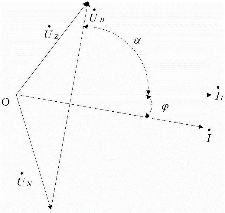
[0042] The phase calibration method of the current measurement of the present invention assumes that the slight change of the distance between the transmitting coil and the receiving coil only affects the imaginary part of the apparent conductivity, and the influence on the real part can be ignored, and the difference between the measured apparent conductivity vector and The current vector is vertical, and the phase difference with the actual measured current vector can be used as the correction amount of the current measurement phase.

[0043] Hereinafter, the phase calibration method for current measurement of the present invention will be described in detail.

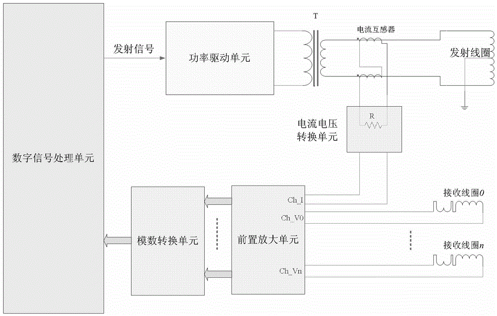
[0044] attached image 3 System block diagram for current measurement of a 3D array induction logging tool. as attached image 3 As shown, the digital signal processing unit (abbreviated as DSP) of the three-dimensional array induction logging tool uses the direct digital frequency synthesis technology to generate ...


PUM


Abstract

The invention relates to a phase calibration method of current measuring for induction logging. The phase calibration method includes that vectors of apparent conductivity under the circumstance that distances between an emitting coil and a receiving coil are different are measured for two times respectively, and current measuring phase errors brought in by a current transformer and a nonlinear element in a current measuring circuit are solved, so that errors brought in by a current measuring link are known accurately and eliminated during calculation. By the phase calibration method, scales and measuring accuracy of an array induction logging instrument are improved.

Description

technical field [0001] The invention relates to an induction well logging method, in particular to a phase calibration method for current measurement used in induction well logging. Background technique [0002] Induction logging uses the principle of mutual inductance of alternating current, and uses the alternating current in the transmitting coil to induce electromotive force in the receiving coil. Since both the transmitting coil and the receiving coil are in the well, the alternating current of the transmitting coil must induce eddy currents in the formation around the wellbore. The eddy current affects the induced electromotive force of the receiving coil, so the electromotive force is related to the strength of the eddy current, that is, to the conductivity of the formation. [0003] The induction logging tool uses a series of coil systems with different coil pitches to measure the same formation, and then obtains the formation conductivity at different radial detecti...

Claims


Application Information

Patent Timeline
IPC IPC(8): E21B49/00E21B47/00
CPCE21B47/00E21B49/00
Inventor 梁小兵肖加奇郝永杰孙煜韩近跃
Owner CNPC GREATWALL DRILLING ENG
Why Eureka
Try Eureka