Novel light guide plate

A light guide plate, a new technology, applied in the field of light guide plates, can solve the problems of weak light output, unsuitable LED primary color lamps and OLEDs, etc., and achieve the effect of improving uniformity and improving uniformity

Inactive Publication Date: 2015-03-25
东莞市现代精工实业有限公司
View PDF5 Cites 4 Cited by
  • Summary
  • Abstract
  • Description
  • Claims
  • Application Information

AI Technical Summary

Problems solved by technology

When LED primary color lamps and OLEDs with weak penetrating power are assembled with the existing light guide plate (installed on the light incident side of the light guide plate), the brightness of the emitted light near the light incident side of the light guide plate (that is, the front end of the light guide plate) is related to the brightness of the light guide plate. There is a large difference between the rear end of the light plate, and the brightness of the light output at the rear end of the light guide plate is very weak, so the light guide plate in the prior art is not suitable for LED primary color lamps and OLEDs with weak penetrating power.

Method used


Image

  • Novel light guide plate
  • Novel light guide plate
  • Novel light guide plate

Examples


Embodiment 1

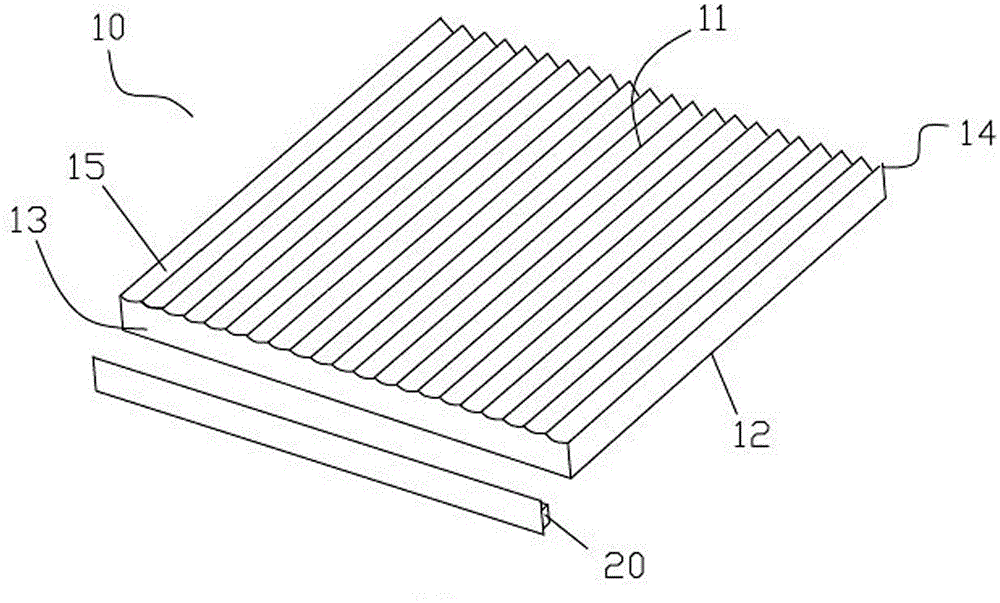
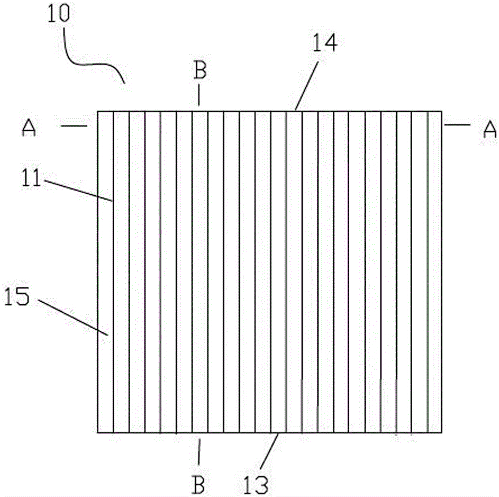
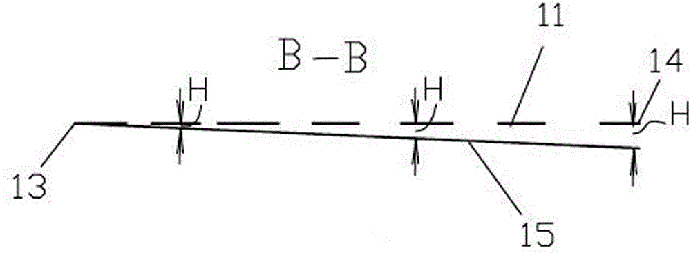
[0027] A new type of light guide plate 10, including a light-emitting surface 11 and a light-reflecting surface 12 that are oppositely arranged. One of the common ends of the light-emitting surface 11 and the light-reflecting surface 12 is the light from the light source 20 that is incident on the light-incident surface 13 of the light-guide plate 10; The opposite end face of the surface 13 is the rear end face 14; a plurality of grooves 15 are formed on the light-emitting surface 11, each groove 15 goes straight from the light-incident face 13 to the rear end face 14, and all the grooves 15 are arranged parallel to each other; the light-incidence face 13 The depth H of the groove 15 is the smallest at , and the depth H of the groove 15 is the largest at the rear end surface 14 . The bottom 16 of the groove is a slope from shallow to deep from the light incident surface 13 to the rear end surface 14 . Strictly speaking, image 3 The bottom 16 of the trench shown in is the lowe...

Embodiment 2

[0031] A new type of light guide plate 10, including a light-emitting surface 11 and a light-reflecting surface 12 that are oppositely arranged. One of the common ends of the light-emitting surface 11 and the light-reflecting surface 12 is the light from the light source 20 that is incident on the light-incident surface 13 of the light-guide plate 10; The opposite end face of the surface 13 is the rear end face 14; a plurality of grooves 15 are formed on the light-emitting surface 11, and each groove 15 goes straight from the light-incident face 13 to the rear end face 14, and all the grooves 15 are arranged parallel to each other; the light-incidence face 13 The groove 15 has the smallest depth H at the rear end surface 14, and the groove 15 depth H is the largest at the rear end surface 14, and the bottom 16 of the groove is a slope from shallow to deep from the light incident surface 13 to the rear end surface 14. Strictly speaking, image 3 The bottom 16 of the trench show...

Embodiment 3

[0035] A new type of light guide plate 10, including a light-emitting surface 11 and a light-reflecting surface 12 that are oppositely arranged. One of the common ends of the light-emitting surface 11 and the light-reflecting surface 12 is the light from the light source 20 that is incident on the light-incident surface 13 of the light-guide plate 10; The opposite end face of the surface 13 is the rear end face 14; a plurality of grooves 15 are formed on the light-emitting surface 11, and each groove 15 goes straight from the light-incident face 13 to the rear end face 14, and all the grooves 15 are arranged parallel to each other; the light-incidence face 13 The groove 15 has the smallest depth H at the rear end surface 14, and the groove 15 depth H is the largest at the rear end surface 14, and the bottom 16 of the groove is a slope from shallow to deep from the light incident surface 13 to the rear end surface 14. Strictly speaking, image 3 The bottom 16 of the trench show...


PUM


Abstract

The invention relates to a backlight source light guide plate, in particular to a novel light guide plate. The novel light guide plate comprises a light emergent surface and a light reflecting surface arranged oppositely, and a common end of the light emergent surface and the light reflecting surface is a light incident surface where light of a light source is emitted to the light guide plate; the end surface opposite to the light incident surface is the rear end surface; a plurality of grooves are formed in the light emergent surface and throughout from the light incident surface to the rear end surface, and all the grooves are arranged in parallel; the depth of the grooves at the light incident surface is smallest, the depth of the grooves at the rear end surface is largest, and the bottom of each groove is a slop getting deep from the light incident surface to the rear end surface. The novel light guide plate can improve the uniformity of outlet light of a weak light source after the light is guided by the light guide plate, and the light will be emitted in a dispersed mode gradually after entering the light guide plate instead of concentrating at the front end of the light guide plate to be emitted, so that the outlet light brightness near the rear end of the light guide plate is basically consistent with that near the front end. The novel light guide plate is particularly suitable for guiding the light of an LED primary color lamp and an OLED with low penetrating capacity.

Description

technical field [0001] The invention relates to a light guide plate, in particular to a novel light guide plate. It is suitable for guiding light to weak light sources (such as LED primary color lamps and OLEDs with weak penetrating power). Background technique [0002] The light guide plate is responsible for converting the point light source of the light-emitting diode (LED for short) into a surface light source with uniform light output. The quality of the light guide plate has a great influence on the optical performance of the backlight source. [0003] The light guide plate is generally a sheet of various shapes. The surface around the sheet is called the side surface, and the other two opposite surfaces are the light-emitting surface and the light-reflecting surface. The LED is assembled with the light guide plate in the form of a side patch, and the light of the LED enters the light guide plate from the side of the light guide plate, which is called the light incid...

Claims


Application Information

Patent Timeline
Patent Type & Authority Applications(China)
IPC IPC(8): G02B6/00F21V8/00F21Y101/02
CPCF21Y2101/00G02B6/0038Y02B20/30
Inventor 顾钧
Owner 东莞市现代精工实业有限公司
Why Eureka
Try Eureka