Five-axis cutter radius compensation method based on post-processing

A tool radius and post-processing technology, which is applied in the direction of instruments, computer control, simulators, etc., can solve the problem of tool length compensation without five-axis tools

Active Publication Date: 2015-03-25
SHANDONG UNIV OF TECH
View PDF4 Cites 23 Cited by
  • Summary
  • Abstract
  • Description
  • Claims
  • Application Information

AI Technical Summary

Problems solved by technology

[0008] The purpose of the present invention is to propose a five-axis tool radius compensation method based on post-processing...

Method used


Image

  • Five-axis cutter radius compensation method based on post-processing
  • Five-axis cutter radius compensation method based on post-processing
  • Five-axis cutter radius compensation method based on post-processing

Examples


Embodiment Construction

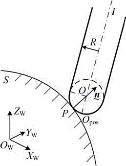
[0023] The preferred embodiment of the five-axis tool length compensation method based on post-processing of the present invention includes:

[0024] A. The basic principle of five-axis tool radius compensation has been studied, and the vectors for the direction of tool radius compensation and the compensation position of the rear tool have been deduced for three commonly used end mills, such as ball nose cutters, flat bottom cutters and ring cutters. equation;

[0025] In the process of five-axis end milling to process curved surfaces, commonly used tool types include ball-end cutters, flat-bottomed cutters, and ring cutters. In order to study the basic principles of five-axis tool radius compensation, the radius compensation directions for the above three types of tools will be deduced below. And compensated flank point vector equation.

[0026] 1. Ball nose cutter radius compensation direction and compensation rear cutter position vector

[0027] Such as figure 1 as show...


PUM


Abstract

The invention discloses a five-axis cutter radius compensation method based on post-processing. The five-axis cutter radius compensation method comprises the steps that firstly, the basic principle of five-axis cutter radius compensation is studied, and the radius compensation direction and vectors of cutter location points obtained after compensation is conducted of three types of common face milling cutters are derived respectively for the three types of common face milling cutters; secondly, a relation equation between preposition cutter location data and the movement data of all axes of a machine tool is established, and a relation equation between cutter location data obtained after compensation is conducted and all the coordinate axes of the machine tool is derived; finally, prost-processing software having a cutter radius compensation function is developed through VisualC++6.0. The five-axis cutter radius compensation method solves the problem of cutter radius compensation of machine tools which do not having the five-axis radius compensation function, the complex process that after the radius size of the cutter is changed, the cutter needs to return a CAM system, a cutter track needs to the regenerated, and post processing needs to be conducted again is avoided, so that the total processing time of parts is shortened, the reusability of a numerical control program is improved, and high engineering application value is achieved.

Description

technical field [0001] The invention relates to a tool radius compensation method for a multi-axis numerical control machine tool, in particular to a post-processing based five-axis tool radius compensation method, which belongs to the field of five-axis numerical control machining. Background technique [0002] Tool compensation is one of the important functions of modern computer numerical control (CNC) system, which can be divided into tool radius compensation and tool length compensation. For two-dimensional contour processing, the current CNC system has the function of tool length and tool radius compensation. However, in the five-axis CNC machining process, the tool radius compensation function is difficult to realize because the tool contact point and the tool axis vector direction are constantly changing. Scholars at home and abroad have done a lot of research on tool radius compensation technology in five-axis CNC machining, and it has been partially applied in som...

Claims


Application Information

Patent Timeline
IPC IPC(8): G05B19/404
CPCG05B19/404
Inventor 徐汝锋陈志同程祥
Owner SHANDONG UNIV OF TECH
Why Eureka
Try Eureka