Method for photocatalytically degrading exhaust gas by electrodeless excimer lamp

A catalytic degradation and excimer technology, which is applied in the field of catalytic degradation of waste gas by electrodeless excimer lamps, can solve the problems of small selection range of electrode materials and luminescent substances, long ignition time and stabilization time, and low utilization rate of light radiation. Small area, simple manufacture, wide application effect

Active Publication Date: 2015-04-01
常州铭瑞环境检测有限公司
View PDF15 Cites 2 Cited by
  • Summary
  • Abstract
  • Description
  • Claims
  • Application Information

AI Technical Summary

Problems solved by technology

[0004] Traditional light sources generally have electrodes. Due to the existence of electrodes in the lamp, a series of problems have been caused: short life, long ignition time and stable time, small selection range of electrode materials and luminescent sub

Method used


Image

  • Method for photocatalytically degrading exhaust gas by electrodeless excimer lamp
  • Method for photocatalytically degrading exhaust gas by electrodeless excimer lamp
  • Method for photocatalytically degrading exhaust gas by electrodeless excimer lamp

Examples


Embodiment 1

[0057] (Example 1, a device for catalytically degrading waste gas with non-polar excimer lights)

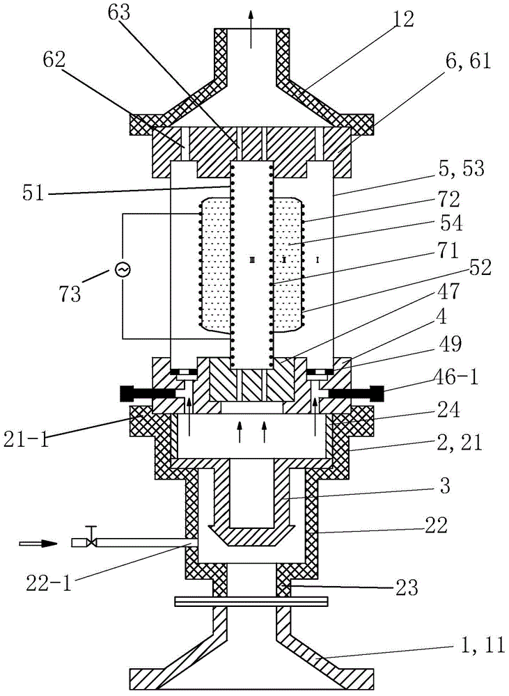
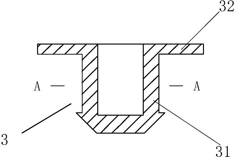
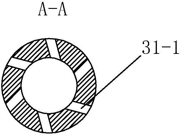
[0058] See figure 1 , The device of the present embodiment of the non-polar excimer light catalytic degradation of exhaust gas includes a gas collection hood 1, a connecting sleeve 2, a gas mixer 3, an inlet distributor 4, a reactor 5, an outlet distributor 6 and an induced draft fan. The air collecting hood 1 includes a lower air collecting hood 11 and an upper air collecting hood 12 . The lower gas collecting hood 11, the gas mixer 3, the reactor 5, the gas outlet distributor 6 and the upper gas collecting hood 12 are arranged sequentially from bottom to top.

[0059] The air inlet of the lower gas collecting hood 11 is connected with the exhaust gas generator gas outlet or the gas storage tank of the gas to be degraded, and the gas outlet of the lower gas collecting hood 11 is connected with the air inlet of the connecting sleeve 2 through a flange. The gas mixer 3 is ...

Embodiment 2

[0094] (Example 2, a method for catalytically degrading exhaust gas by non-polar excimer lights)

[0095] The method for catalytically degrading waste gas by light-emitting excimer light in this embodiment adopts the device described in Embodiment 1, and the through-hole plug used in the air inlet distributor 4 is a blind hole plug 48 . The inner electrode 71 is made of metal sheet, and the outer electrode 72 is made of metal mesh.

[0096] The process of photocatalytic degradation of waste gas by non-polar excimer lights is as follows: the waste gas from the waste gas generator or the waste gas storage tank is initially mixed by the gas mixer 3, and then further mixed evenly by the air inlet distributor 4, and then enters the reactor under the action of the induced draft fan 5 for purification. A sampling port is set at the outlet of the reactor 5 at a distance of 1m from the reactor, and the concentration of the reacted gas is detected by an online gas analyzer, and the gas...

Embodiment 3

[0103] (Example 3, a method for catalytically degrading exhaust gas by non-polar excimer lights)

[0104] The method for catalytically degrading waste gas by light-emitting excimer light in this embodiment adopts the device described in Embodiment 1, and the through-hole plug used in the air inlet distributor 4 is a porous plug 47 . The inner electrode 71 is made of metal mesh, and the outer electrode 72 is made of metal sheet.

[0105] See Figure 7 , in this example, the degradation flow dynamics simulates dimethylamine waste gas, and the initial concentration is 3745 mg / m 3 , the method for degrading exhaust gas specifically includes the following steps:

[0106] ① Vacuum the gas filling zone II, and then fill it with Kr : Cl 2 =350:1, total pressure 205torr.

[0107]② Turn on the high-voltage power supply 73, apply an external voltage of 6kV, and a power of 50W. The gas-filled mixture in zone II is excited to generate excimer ultraviolet light to radiate to the reactio...


PUM


Abstract

The invention discloses a method for photocatalytically degrading exhaust gas by an electrodeless excimer lamp. A used reactor comprises three quartz medium layers, an inner electrode, an outer electrode and a high-voltage power supply. The three quartz medium layers comprise a first quartz tube, a second quartz tube and a third quartz tube which are coaxial and are sequentially arranged from inside to outside; the internal cavity of the first quartz tube is a reaction region III; a closed annular cavity is formed between the second quartz tube and the first quartz tube and serves as a gas filled region II; a reaction region I is formed between the third quartz tube and the second quartz tube. During the photocatalytic degradation of the exhaust gas, gas of the gas filled region II is excited to generate excimer UV light which radiates towards the direction of the reaction region I and the direction of the reaction region III, and the exhaust gas to be degraded fully passes through the reaction region I or reaction region III or enters the reaction region I and the reaction region III in a divided-flow manner and is degraded under the action of excimer ultraviolet radiation.

Description

[0001] This application is a divisional application of the invention patent application with the application number 201310089087.X and the application date is March 20, 2013, and the invention name is "device and method for catalytic degradation of exhaust gas by non-polar excimer light". technical field [0002] The invention relates to the field of waste gas degradation, in particular to a method for catalytically degrading waste gas by an electrodeless excimer light. Background technique [0003] Ultraviolet light source has been widely used in the fields of microelectronics, medicine, chemical industry, sanitation and environmental protection, and has become a basic and key technology. All of the above applications require the light source to have a narrow radiation spectrum and a certain radiation intensity. For traditional medium and high-pressure mercury lamps, the radiation spectrum has a wide range of wavelengths (from the ultraviolet region to the visible region),...

Claims


Application Information

Patent Timeline
IPC IPC(8): B01D53/86B01D53/76
Inventor 叶招莲孙建华赵洁黄红缨侯洁
Owner 常州铭瑞环境检测有限公司
Why Eureka
Try Eureka