LED (Light-Emitting Diode) lamp

An LED lamp and lamp body technology, which is applied to lighting and heating equipment, semiconductor devices of light-emitting elements, point-shaped light sources, etc. Angled glow effect

Active Publication Date: 2015-04-01
OPPLE LIGHTING
View PDF8 Cites 3 Cited by
  • Summary
  • Abstract
  • Description
  • Claims
  • Application Information

AI Technical Summary

Problems solved by technology

However, the traditional LED light source is either not bright enough, or the light angle is not large enough.

Method used


Image

  • LED (Light-Emitting Diode) lamp
  • LED (Light-Emitting Diode) lamp
  • LED (Light-Emitting Diode) lamp

Examples


Embodiment Construction

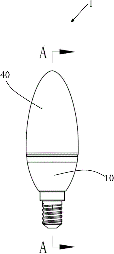
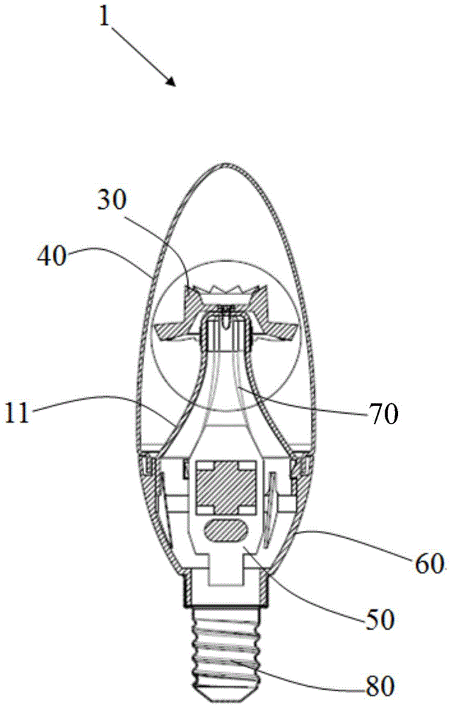
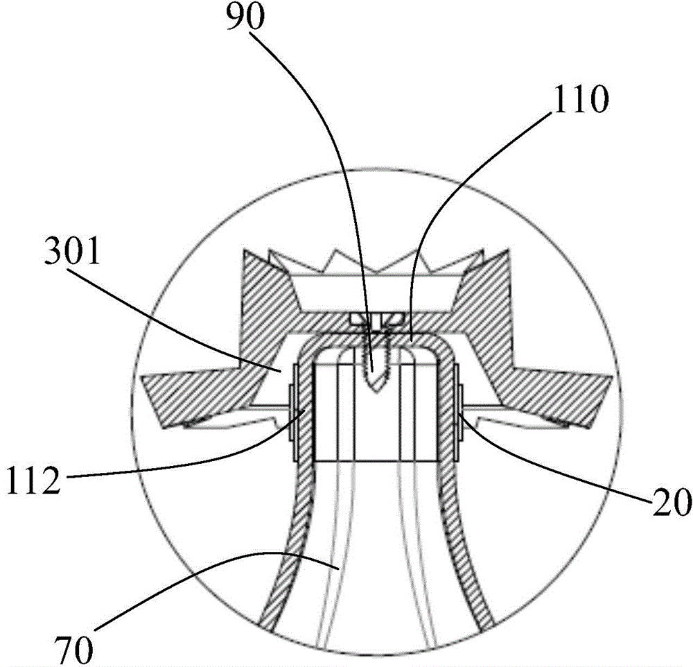
[0021] Please refer to Figure 1 to Figure 5 As shown, the LED lamp 1 of the preferred embodiment of the present invention includes a lamp body 10 , a light source 20 and a lens 30 . The lamp body 10 has a protruding protruding part 11, the protruding part 11 has a top surface 110 and a side surface 112 located at the lower part of the top surface 110, at least part of the light source 20 is fixed on the side surface 112 of the protruding part 11, and the light source 20 has at least part of the light passing through the lens 30 After ejaculation. In a preferred embodiment of the present invention, at least part of the light source 20 is located on the side 112 of the protruding part 11, and at least part of the light from the light source 20 is emitted through the lens 30, so that the LED lamp 1 of the present invention can not only emit light at a large angle, but also At the same time, the luminous effect of the LED lamp can be adjusted conveniently through the lens 30 . ...


PUM


Abstract

The invention discloses an LED (Light-Emitting Diode) lamp which comprises a light source and a lens, wherein the lens comprises a hollow accommodating cavity for accommodating the light source, a first optical element positioned at the periphery of the accommodating cavity and a second optical element positioned below the first optical element; the outer diameter of the second optical element is greater than that of the first optical element; the accommodating cavity penetrates through the second optical element along the vertical direction and is partially positioned in the first optical element; the light source is partially positioned in the accommodating cavity and is partially exposed out of the accommodating cavity.

Description

【Technical field】 [0001] The invention relates to an illuminating device, in particular to an LED lamp. 【Background technique】 [0002] LED bulbs or candle lamps are a common light source in modern lighting design, and are often used in various lamps, such as dining chandeliers, downlights, crystal lamps, and so on. However, the traditional LED light source is either not bright enough, or the angle of light is not large enough. [0003] Therefore, in order to overcome the above defects, it is necessary to provide an improved LED lamp. 【Content of invention】 [0004] The object of the present invention is to provide an LED lamp. [0005] In order to achieve the above object, the present invention adopts the following technical solutions: an LED lamp, including a light source and a lens, the lens includes a hollow housing cavity for placing the light source, a first optical element located around the housing cavity, and a first optical element located at the first The sec...

Claims


Application Information

Patent Timeline
Patent Type & Authority Applications(China)
IPC IPC(8): F21S2/00F21V5/04F21V23/00F21V17/12F21Y101/02
CPCF21K9/20F21V5/048F21V17/12F21V23/003F21Y2101/00
Inventor 程争光王洪波白坤王可勇
Owner OPPLE LIGHTING
Why Eureka
Try Eureka