
Rotating shaft limiting device

A technology of limit devices and rotary shafts, which is applied in the field of limit devices and rotary shaft limit devices, can solve the problems of increasing the size of the end-execution structure, increasing the size and complexity of the mechanism, and improving the degree of versatility and scalability , Space-saving, reliable limit effect

Active Publication Date: 2015-04-08
NINGXIA KOCEL MACHINE TOOL ACCESSORIES
View PDF6 Cites 0 Cited by
  • Summary
  • Abstract
  • Description
  • Claims
  • Application Information

AI Technical Summary

Problems solved by technology

The common limit method is to add a hard limit to the end actuator. However, the problem with the above structure is that the end actuator is often a relatively weak link in the entire slewing device. In order to offset the force of the hard limit on the end actuator , it is necessary to increase the size of the end-execution structure
This virtually increases the size and complexity of the mechanism

Method used


Image

  • Rotating shaft limiting device
  • Rotating shaft limiting device
  • Rotating shaft limiting device

Examples


Embodiment Construction

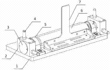
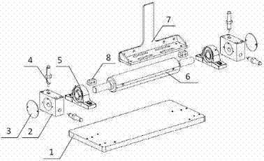
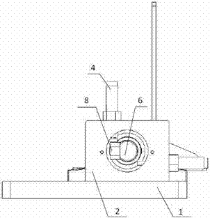
[0013] Attached below figure 1 , attached figure 2 , attached image 3 The present invention is further analyzed.

[0014] A rotary shaft 6 passes through two bearings with seats 5, and the bearings with seats 5 are fixed on the fixed plate 1, and the two limit seats 2 are fixed on the fixed plate 1, and the cavities on the two limit seats 2 and the rotary shaft 6 coaxial arrangements. Two hydraulic buffers 4 are installed on each limit seat 2, and a sealing plate 3 is installed on the end surface of the limit seat 2, which is used to block the end hole of the limit block after installation and debugging, so as to ensure the Safety protection for moving parts. An end effector 7 is fixed on the rotary shaft 6 , a plane is machined on both ends of the rotary shaft 6 and a limit block 8 is installed on the plane. The limit block 8 can be made into any shape according to actual needs to realize any setting at an angle of 0-360°. The limit block 8 rotates with the rotary shaf...


PUM


Abstract

The invention relates to a rotating shaft limiting device. The rotating shaft limiting device is composed of a baseplate, limiting seats, closure plates, hydraulic buffers, bearing seats, a rotating shaft, an end execution unit and limiting blocks. The end execution unit is fixedly arranged on a curved surface of the rotating shaft; the bearing seats are arranged at two ends of the rotating shaft respectively; the bearing seats are fixedly arranged on the baseplate; the limiting seats are arranged at two ends, away from the rotating shaft, of the bearing seats respectively; the limiting seats are fixed on the baseplate; one hydraulic buffer is arranged on the upper portion of each limiting seat; one closure plate is arranged on the end face of each limiting seat; the limiting blocks are arranged on the end faces of two ends of the rotating shaft respectively. The rotating shaft limiting device has the advantages that the problem that the conventional rotating structures are complex in limiting is solved, and the rotating shaft limiting device is space saving, safe, reliable in limiting and convenient to operate; a buffer function is realized, random limiting in a range of 0-360 degrees is realized, and smooth transition of actions during limiting is guaranteed; no impact occurs, the end execution unit is avoided being oversize, and universality degree and expansibility of the limiting device are improved.

Description

technical field [0001] The invention relates to a limiting device for roller conveying equipment, in particular to a limiting device for a rotary shaft, which belongs to the field of machine tool auxiliary machines. Background technique [0002] In the field of mechanical processing, rotary motion is the most common type of motion in machinery. Usually, the rotary shaft rotates relatively around the rotary bearing seat to achieve the expected action. However, in many industrial practical applications, the continuous rotation of the rotary shaft is often not required. In order to ensure that the equipment can complete a specific movement, it is usually necessary to limit the moving parts. The common limit method is to add a hard limit to the end actuator. However, the problem with the above structure is that the end actuator is often a relatively weak link in the entire slewing device. In order to offset the force of the hard limit on the end actuator , it is necessary to in...

Claims


Application Information

Patent Timeline
Patent Type & Authority Applications(China)
IPC IPC(8): B23Q7/00
CPCB23Q7/05
Inventor 赵亚宁吴乐俞科梁珊
Owner NINGXIA KOCEL MACHINE TOOL ACCESSORIES
Learn More