Method and system for ring joint configuration of jointing wall

A splicing wall and looping technology, applied in the field of splicing walls, can solve problems such as poor signal display and link failure, and achieve the effect of avoiding loop configuration errors

Inactive Publication Date: 2015-04-08
GUANGDONG VTRON TECH CO LTD
View PDF4 Cites 7 Cited by
  • Summary
  • Abstract
  • Description
  • Claims
  • Application Information

AI Technical Summary

Problems solved by technology

[0004] Based on this, it is necessary to provide a method and system for loop connection configuration of a splicing wall for the problems of link failure and poor signal display due to loop configuration errors

Method used


Image

  • Method and system for ring joint configuration of jointing wall
  • Method and system for ring joint configuration of jointing wall

Examples


Embodiment Construction

[0016] The present invention will be described in further detail below in conjunction with the embodiments and accompanying drawings, but the embodiments of the present invention are not limited thereto.

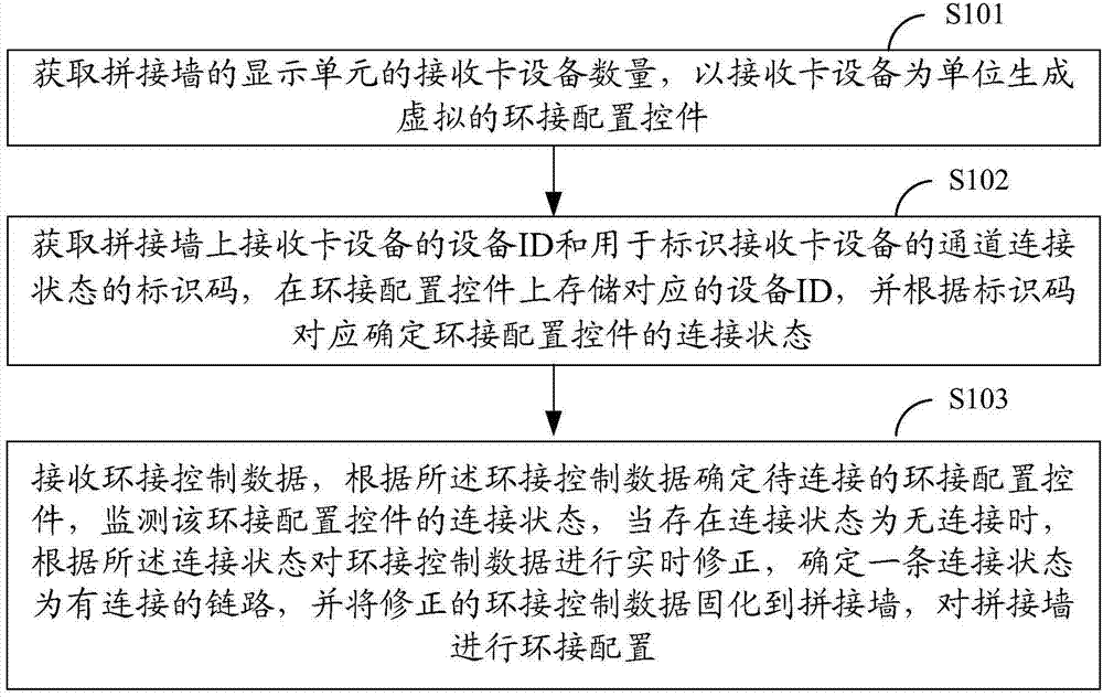
[0017] Such as figure 1 As shown, it is a schematic flow chart of an embodiment of the method for splicing wall loop configuration according to the present invention, including:

[0018] Step S101: Obtain the number of receiving card devices of the display unit of the splicing wall, and generate a virtual loop connection configuration control in units of receiving card devices;

[0019] A splicing wall is composed of multiple display units, each display unit includes multiple receiving card devices, and each receiving card device includes multiple channels. The purpose of this step is to establish a virtual video wall model based on the receiving card device of the video wall. Video walls can be LED video walls.

[0020] Step S102: Obtain the device ID of the receiving ca...


PUM


Abstract

The invention relates to a method and a system for ring joint configuration of a jointing wall. The method comprises the following steps that the number of receiving card equipment of display units of the jointing wall is obtained, and a virtual ring joint configuration control is generated by using the receiving card equipment as the unit; the equipment ID (identity) of the receiving card equipment on the jointing wall and marking codes used for marking the passage connecting state of the receiving card equipment are obtained, the corresponding equipment ID is stored on the ring joint configuration control, and the connecting state of the ring joint configuration control is correspondingly determined according to the marking codes; ring joint control data is received, the ring joint configuration control to be connected is determined according to the ring joint control data, the connecting state of the ring joint configuration control is monitored, when the unconnected connecting state exists, the ring joint control data is subjected to real-time correction according to the connecting state, a link with the connected connecting state is determined, the corrected ring joint control data is cured to the jointing wall, and the jointing wall is subjected to ring joint configuration. The method and the system have the advantage that the ring joint configuration accuracy is improved.

Description

technical field [0001] The present invention relates to the field of splicing walls, in particular to a method and system for loop configuration of a splicing wall. Background technique [0002] With the development of video wall display technology, the application of video wall technology is becoming more and more extensive. The application fields of splicing wall display have covered various fields such as public display, transportation dispatching and commanding, weather monitoring, power and telecommunications monitoring, fire monitoring and commanding, and military commanding. The splicing wall system is usually spliced ​​by multiple display units, and a control host sends control commands to multiple display units to control the image display of the entire splicing wall. The requirement for distributed processing capability on the video wall system is getting higher and higher. Led redundancy configuration and unit configuration requirements are getting higher and hi...

Claims


Application Information

Patent Timeline
Patent Type & Authority Applications(China)
IPC IPC(8): G06F3/14
CPCG06F3/1446
Inventor 林良辉陈永权吴细平
Owner GUANGDONG VTRON TECH CO LTD
Why Eureka
Try Eureka