Constant torque boosting and pulling locker and chassis bracket device and cabinet

A technology of fixed torque and locker, which is applied in the direction of support structure installation, electrical equipment shell/cabinet/drawer, electrical components, etc., and can solve the problem that the locker cannot assist the insertion and removal of the chassis

Active Publication Date: 2017-09-22
CHINA AVIATION OPTICAL-ELECTRICAL TECH CO LTD
View PDF3 Cites 0 Cited by
  • Summary
  • Abstract
  • Description
  • Claims
  • Application Information

AI Technical Summary

Problems solved by technology

[0004] The purpose of the present invention is to provide a fixed torque boosting and pulling out locking device to solve the problem that the existing locking device for the chassis cannot assist the insertion and extraction of the chassis

Method used


Image

  • Constant torque boosting and pulling locker and chassis bracket device and cabinet
  • Constant torque boosting and pulling locker and chassis bracket device and cabinet
  • Constant torque boosting and pulling locker and chassis bracket device and cabinet

Examples


Embodiment Construction

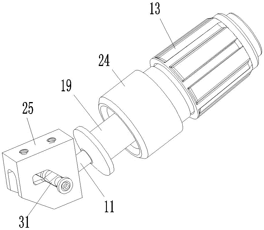
[0029] Embodiments of torque-assisted pull-out lockers, such as Figure 2-12 As shown, the locking device includes a lock rod 11, a screw sleeve 12, a screw cap 13, a transmission steel ball 14, a transmission piece 15, a pressing piece 16, a force limiting spring 17, a spring support sleeve 18, an output sleeve 19, and a transmission seat 20 , ball 21, push spring 22, drive sleeve 23, lock cap 24 and lock seat 25.

[0030] The front end of the locking rod 11 is provided with a hinge hole and a threaded section is provided between the two ends.

[0031] The position between the two ends of the screw sleeve 12 is provided with an internal thread segment, which corresponds to the thread segment on the lock bar 11, and the screw sleeve 12 is exactly through the connection between its internal thread segment and the thread segment of the lock bar 11. Cooperate and threadedly assembled on the lock rod 11, because both of them are not all provided with threads, so the rear end of t...


PUM


Abstract

The invention relates to the field of modular electrical cabinets, in particular to a constant torque boosting and pulling locker, a chassis bracket device and a cabinet. The locking device includes a lock rod and a lock cap. The screw sleeve is threaded on the lock rod. The rear part of the screw sleeve is equipped with a constant torque drive mechanism, and the front part is equipped with an output sleeve. The constant torque drive mechanism includes a force limiting spring and a pressure plate. , the transmission piece and the rotatable screw cap, there is a retaining wall between the two ends of the screw cap, the barrier wall is provided with a transparent installation hole and a transmission steel ball is installed in the installation hole, the pressing piece and the transmission piece are separately located in the On both sides of the retaining wall, the transmission plate is in unrotatable fit with the screw sleeve and there is a ball groove corresponding to the steel ball on it, and the force limiting spring is installed between the side of the pressing plate away from the steel ball and the screw sleeve; the output sleeve The front part is equipped with a locking hook matching structure, and a rotating transmission mechanism is provided between the screw sleeve and the inversion edge of the transmission sleeve. The invention solves the problem that the existing locker for the chassis cannot assist the insertion and removal of the chassis.

Description

technical field [0001] The invention relates to the field of modular electrical cabinets, in particular to a constant torque boosting and pulling locker, a chassis bracket device and a cabinet. Background technique [0002] With the development of modularization and miniaturization of various electronic equipment, electronic equipment cabinets have been widely used in electronic equipment cabinets (electrical cabinets). In the specific use process, in order to realize the overall loading and unloading and replacement, the cabinet is equipped with a chassis bracket device in layers. The electrical connector provided in the cabinet cooperates with the electrical connector on the chassis bracket provided in the cabinet to realize the introduction of the electronic equipment chassis. This structure requires that the electronic equipment chassis must have a reliable fixing mechanism when it is assembled on the cabinet. Therefore, the chassis The bracket devices all include a bra...

Claims


Application Information

Patent Timeline
Patent Type & Authority Patents(China)
IPC IPC(8): H05K7/14H05K5/00
Inventor 周卫可吕云朋陈建超杨成博
Owner CHINA AVIATION OPTICAL-ELECTRICAL TECH CO LTD
Why Eureka
Try Eureka