Cardiac valve support structure

A heart valve and valve technology, applied in the direction of heart valve, valve annulus, medical science, etc., can solve the problems of difficult vascular system guidance, difficult heart valve, difficult to provide placement contours, etc.

Inactive Publication Date: 2015-04-08
M阀门技术有限公司
View PDF10 Cites 1 Cited by
  • Summary
  • Abstract
  • Description
  • Claims
  • Application Information

AI Technical Summary

Problems solved by technology

The general anatomy of the mitral annulus also makes it difficult to properly hold a replacement heart valve in place
However, increasing the constricted deployment profile will make intravascular placement more risky for the patient and more difficult to guide through the vasculature with larger diameter placement systems
[0009] Some attempts have been made to place and implant a one-piece replacement mitral valve, but it has been difficult to provide a device that can be collapsed with a sufficiently small deployment profile and still expand and hold in place in the mitral valve via a vascular access site. device

Method used


Image

  • Cardiac valve support structure
  • Cardiac valve support structure
  • Cardiac valve support structure

Examples


Embodiment Construction

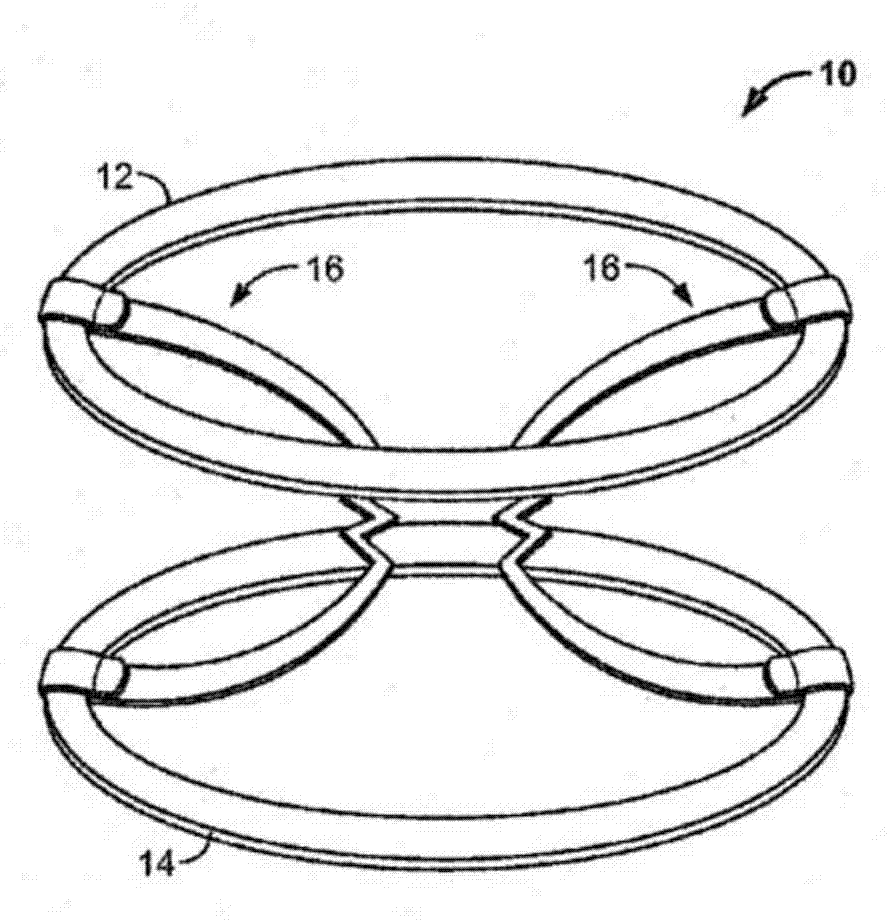
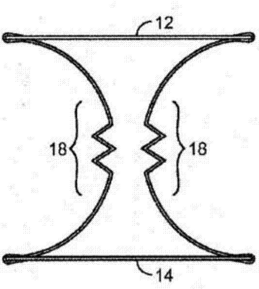
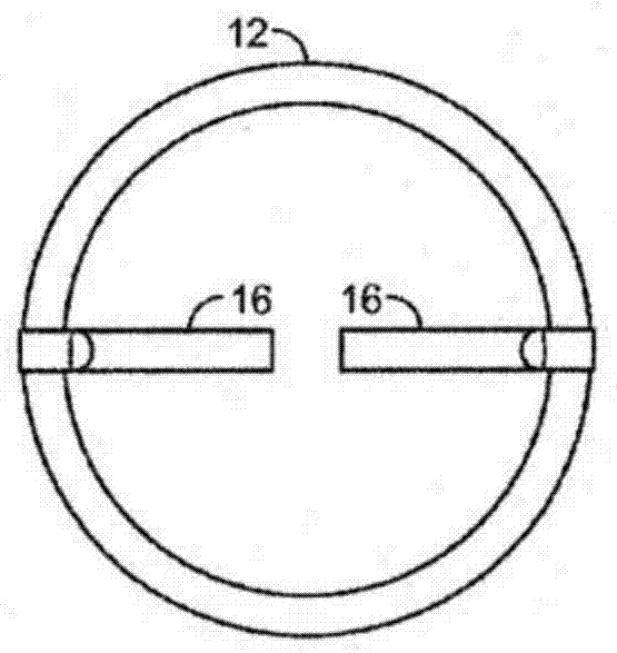
[0141] The present invention generally relates to heart valve support structures adapted for implantation in or near a native heart valve or native valve annulus, and for providing support for a replacement heart valve. The support structure is adapted to interact with the replacement heart valve to secure it at an implantation site in or near the native valve or native valve annulus. In some embodiments, the support structure is adapted to be positioned in or near the mitral valve annulus and is adapted to interact with a subsequently placed replacement heart valve to hold the replacement valve in place to replace the native mitral valve. Function. In a particularly preferred embodiment, the replacement heart valve is an artificial aortic valve.

[0142] The present invention also provides a two-step endovascular implantation procedure for replacing a patient's native mitral valve. Typically, the support structure is first positioned in or near the mitral valve annulus and ...


PUM


Abstract

The present invention is primarily directed to a cardiac valve support adapted for endovascular delivery to a cardiac valve, comprising first and second support elements and at least two bridging members that extend from the first support element to the second support element. The valve support may further comprise additional elements aimed at improving the stability of the device following implantation in the region of a cardiac valve annulus, particularly the mitral valve annulus.

Description

technical field [0001] The present invention relates to various improvements to heart valve support structures comprising two support elements interconnected by two or more bridging members. Background technique [0002] Heart valve regurgitation occurs when the heart leaflets do not close completely during systole. When the heart contracts, blood flows back through the leaflets that do not close properly. For example, mitral valve regurgitation occurs when blood flows back through the mitral valve and into the left atrium during ventricular contraction. [0003] In some cases, regurgitation occurs due to disease of the valve leaflets (eg, primary or "organic" regurgitation). Regurgitation is also caused by dilation of the left ventricle, which causes secondary dilation of the mitral annulus. Dilation of the annulus causes the mitral valve leaflets to spread apart and create poor tip cooptation and secondary leaks, or so-called "functional regurgitation". [0004] Curren...

Claims


Application Information

Patent Timeline
Patent Type & Authority Applications(China)
IPC IPC(8): A61F2/24
CPCA61F2/2409A61F2/2445A61F2/2418A61F2250/006
Inventor M.布克宾德J.洛根S.杜比A.塔比斯赫维茨A.埃夫特尔
Owner M阀门技术有限公司
Why Eureka
Try Eureka