Vessel and lumen expander attachment for use with an electromechanical driver device

a technology of vascular expanders and driver devices, which is applied in the field of vascular expanders, can solve the problems of inability to insert devices, large hospitalization and tremendous rehabilitation, and the inability to fully invasive procedures, and achieve the effect of slowing down the potential re-stenosis of the vessel and increasing fluid flow

Inactive Publication Date: 2002-02-19
DORROS GERALD M D
View PDF89 Cites 1141 Cited by
  • Summary
  • Abstract
  • Description
  • Claims
  • Application Information

AI Technical Summary

Benefits of technology

Once the attachment is properly positioned, the surgeon begins by actuating the finger trigger in the handle of the electromechanical driver device, causing the flexible drive shaft within the flexible shaft to rotate. The coupling of the attachment with the distal end of the flexible drive shaft causes the discontinuously threaded elongate rod to rotate (and only the discontinuously threaded elongate rod). The nuts then advance towards one another, causing the spokes to rotate out...

Problems solved by technology

This fully invasive procedure often requires significant hospitalization and tremendous rehabilitation.
This procedure has been widely accepted and is only untenable in situations where the stenosis has occurred to such a great extent that the device cannot be inserted.
One of the most important drawbacks of the balloon catheter design is that the means for inflating the volume, and the manner in which the volume is inflated, completely blocks the flow of fluids through the vessel during the procedure.
This failure is inherent in the design by virtue of the fact that the balloon must occlude the vessel in order to apply the pressure to the walls.
This failure relates to the gathering of information about the expansion of the vessel walls.
The inclusion of narrow passages through the expanding volume, especially in the case of a balloon having a cannulated structure, results in a very unreliable interior pressure to diameter relationship.
Unfortunately, it is also not always the case that the one time expansion of the vessel (during the surgical intervention) continues to remain effective over a long period.
The remote installation of a stent is difficult, but several designs have been offered in which the stent is delivered in a collapsed form, and is then irreversibly expanded into position by means incorporated into the insertion tube.
Continued stenosis of the vessel around, and...

Method used


Image

  • Vessel and lumen expander attachment for use with an electromechanical driver device
  • Vessel and lumen expander attachment for use with an electromechanical driver device
  • Vessel and lumen expander attachment for use with an electromechanical driver device

Examples


first embodiment

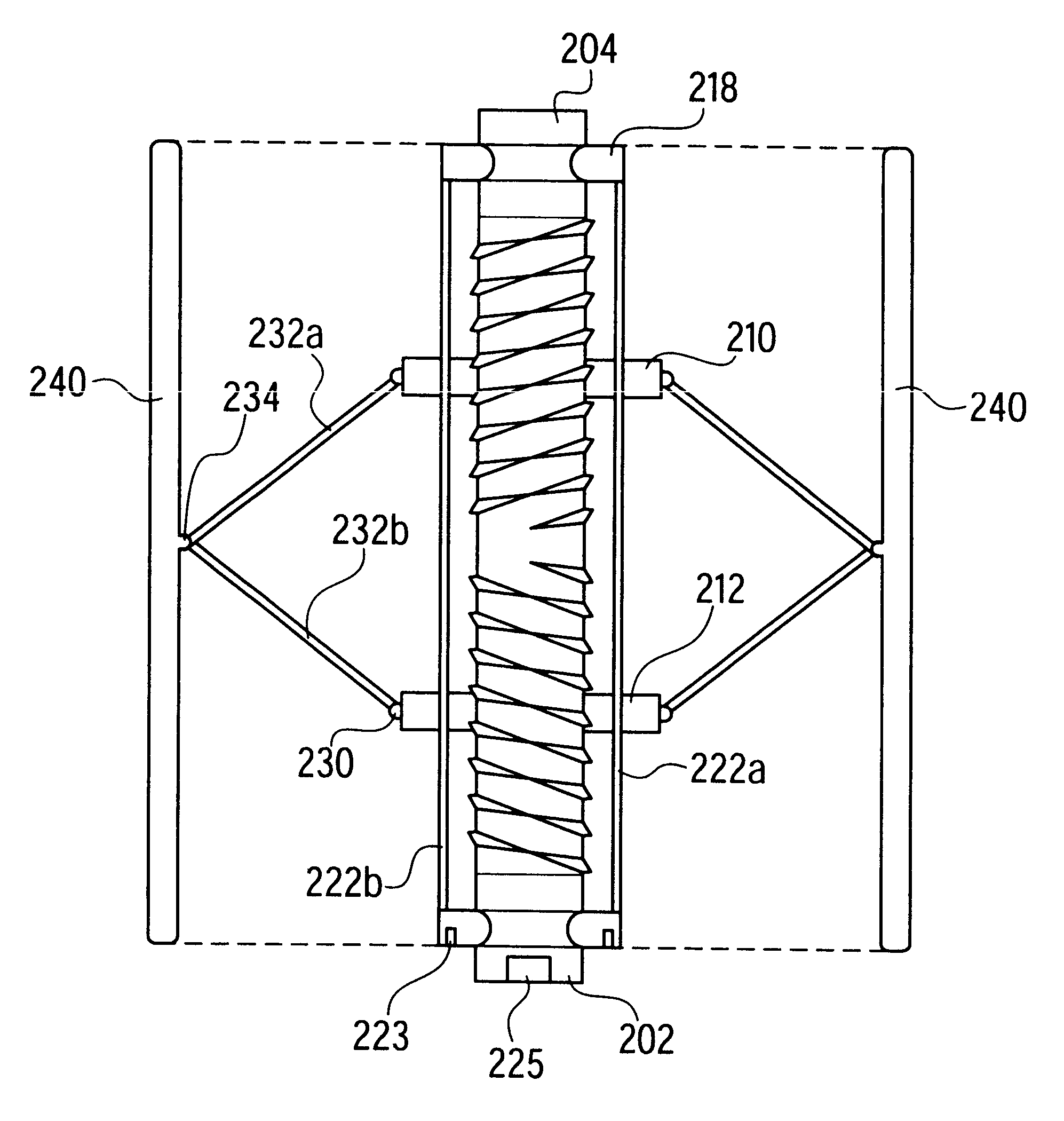
Referring now to FIGS. 3a and 3b, the present invention is provided in a pair of cross-sectional views; the first illustrating the attachment in a semi-expanded position, and the second illustrating the attachment in a fully extended position. In this embodiment, each of the nuts 210,212 are coupled to one another at a plurality of circumferential sites by means of a series of flexible joints, or pivots 230. More particularly, each of the pivots 230 is formed by a pair of spokes 232a,232b, one 232a of which is attached to the first nut 210 at a circumferential site thereon, and the other 232b being similarly mounted on the second nut 212. Each spoke 232a,232b is fixed at one end to its respective nut 210,212 by a joint which permits the spoke to rotate radially outwardly. At the other end of each spoke 232a,232b, each is coupled by a similar joint 234 to the distal end of the corresponding opposing spoke, such that the connected spokes may expand radially outwardly in an umbrella-li...

second embodiment

Referring now to FIGS. 4a and 4b, a second embodiment is shown. It shall be understood that the spokes 232a,232b need not be directly coupled with one another, but instead may be coupled together by a third pin 236 which is jointed with the distal ends of the spokes 232a,232b, and which moves radially with respect to the rod 200 in accordance with the motion of the nuts 210,212, but which remains parallel to the rod 200.

In both embodiments, the distal ends of the spokes 232a,232b are also coupled with a flexible tubular material 240 which forms a continuous expanding surface as the nuts 210,212 are brought together. More particularly, the flexible tube 240 includes sufficient axial rigidity (for example, by means of axial ribs, not shown), but sufficient radial expandability such that the expanding spokes 232a,232b create a cylindrical structure having a constant diameter and a series of radially spaced apart spokes extending from the inner surface of the flexible tube 240 to the ce...


PUM


Abstract

A selectively coupleable and remotely actuateable surgical attachment for use with an electromechanical driver device for use in expanding occluded vessels and lumens. The attachment includes an axial rod which is coupleable to the electromechanical driver device, and which is selectively rotateable in accordance with the action of the electromechanical driver device. The rod is also threaded in opposing orientations at either end thereof. A pair of nuts are mounted to the rod, and specifically on the opposing threads. The rod and nuts are disposed within an axial track which permits the rod to turn, but constrains the rotational motion of the nuts, thereby permitting the nuts to move axially along the threadings of the rod when the rod turns. Attached to the nuts are a series of jointed spokes which are coupled to a flexible tubular shroud which surrounds the entire assembly. The jointed spokes are radially extended and retracted in accordance with the motion of the nuts in an umbrella-like fashion in accordance with the actuation of the electromechanical driver device. The radial expansion of the flexible tubular shroud provides the necessary force to expand an occluded vessel or lumen.

Description

1. Field of the InventionThe present invention relates generally to an attachment for use with an electromechanical driver device, and more specifically to a vascular expander device which is insertable, expandable, collapsible, and removable within and from a vascular, lumen, or similar vessel by means of a remote electromechanical driver device.2. Description of the Prior ArtUpon identification of a stricture and / or stenosis in an artery, gastrointestinal tract, bowel, or other vessel of the body (for another important example, the bile duct) several treatment actions may be selected. Surgical intervention may include fully invasive procedures such as bypasses in which supplemental vessels are transplanted from other regions of the body, or in less frequent circumstances, artificial supplemental structures are implanted. This fully invasive procedure often requires significant hospitalization and tremendous rehabilitation. For these reasons, it has been a goal of the industry to m...

Claims


Application Information

Patent Timeline
IPC IPC(8): A61M29/00A61B17/00A61F2/82A61F2/95A61M25/00
CPCA61M29/02
Inventor WHITMAN, MICHAEL P.
Owner DORROS GERALD M D
Why Eureka
Try Eureka