Unlock instant, AI-driven research and patent intelligence for your innovation.

push switch

A switch and cover member technology, applied in the direction of electrical switches, electrical components, emergency housings, etc., can solve the problems of poor operation feeling, timing deviation, etc., and achieve the effect of simple structure and improved push-in strength

Active Publication Date: 2017-04-12
ALPS ALPINE CO LTD
View PDF5 Cites 0 Cited by
  • Summary
  • Abstract
  • Description
  • Claims
  • Application Information

AI Technical Summary

Problems solved by technology

When the hold of the metal cover 933 relative to the case 927 is weakened, the operation can be performed, but the timing of the contact or separation between the central electrode and the side electrodes through the contact piece 930 may be deviated or the operating feeling may be deteriorated. bad

Method used


Image

  • push switch
  • push switch
  • push switch

Examples


no. 1 approach

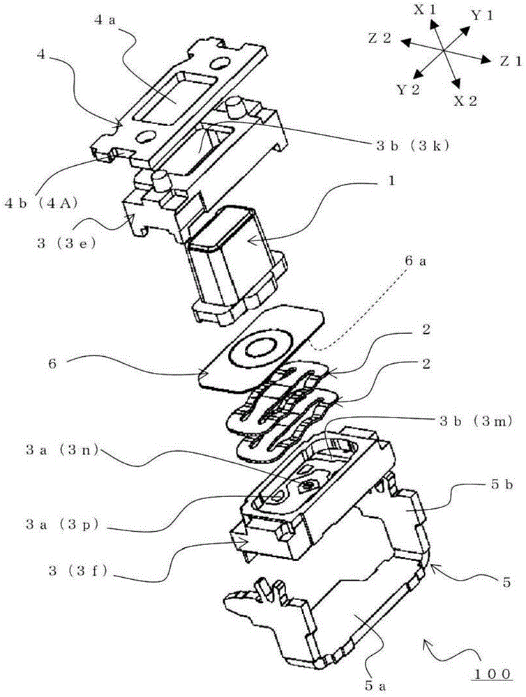
[0157] The push switch 100 in the first embodiment will be described below.

[0158] First, use Figure 1 to Figure 10 The configuration of push switch 100 in this embodiment will be described. figure 1 It is an exploded perspective view showing the structure of the push switch 100 in the first embodiment. figure 2 It is a figure which shows the appearance of the push switch 100 in 1st Embodiment, figure 2 (a) is a perspective view showing the appearance of the push switch 100, figure 2 (b) is for from figure 2 (a) is a plan view showing the push switch 100 as viewed from the Z2 direction side. image 3 It is a figure which shows the example of the state which mounted the push switch 100 in 1st Embodiment on a board|substrate, image 3 (a) is for from figure 2 The shown Z2 direction side view push switch 100 is a plan view showing the state of the assembly example of the board, image 3 (b) is for from image 3 (a) is a plan view showing an example state of mount...


PUM


Abstract

The present invention provides a horizontal-push-type push switch which has the tolerance for push operations from the front side after a substrate is mounted. A push switch (1) is composed of: an operation member (1); a movable contact member (2); a case (3) having a fixed contact part (3a) and a space part (3b) which can accommodate the operation member and the movable contact member and is opened at the front side; a front cover member (4) which covers the space part; and a rear cover member (5) which has a base part (5a) covering the back side of the case, and arm parts (5b) extending from both sides of the base part towards the front side. In the push switch, the front cover member is provided with a through hole (4a) through which the operation member projects, and an engagement part (4A), i.e. an engagement concave part (4b), two ends of which are engaged with the arm parts of the rear cover member. The engagement concave part of the front cover is engaged with the arm parts of the rear cover member, so that the front cover member and the rear cover member are integrated.

Description

technical field [0001] The present invention relates to a push switch, and more particularly, to a side push type push switch that is resistant to a push operation from the front side after mounting on a substrate. Background technique [0002] Recently, among portable electronic devices, thin products are increasing. Among the push switches arranged on the side of such thin portable devices, side push type push switches are often used. [0003] As such a push switch, a push switch described in Patent Document 1 below is known. [0004] Below, use Figure 32 , the push switch 900 described in Patent Document 1 will be described. Figure 32 It is a sectional view showing the structure of the push switch 900 described in Patent Document 1. FIG. [0005] The push switch 900 described in Patent Document 1 is a push button switch composed of a case 927 including a center electrode and side electrodes, a contact piece 930 of a conductive metal plate, a dustproof sheet 931 , a ke...

Claims


Application Information

Patent Timeline
Patent Type & Authority Patents(China)
IPC IPC(8): H01H13/14H01H13/04H01H13/02
CPCH01H13/04H01H2223/01H01H13/52
Inventor 田泽俊彦浅井裕久小谷胜彦须田雅昭小林洁忠古山丈夫岛谷胜明末田耕造伊藤义尚佐藤秀隆
Owner ALPS ALPINE CO LTD