
Automatic moving device

A technology of automatic movement and threaded connection, which is used in fluid pressure actuation devices, feeding devices, transportation and packaging, etc. Effect

Inactive Publication Date: 2015-04-22
安徽池州瑞强塑业有限公司
View PDF0 Cites 2 Cited by
  • Summary
  • Abstract
  • Description
  • Claims
  • Application Information

AI Technical Summary

Problems solved by technology

[0003] The technical problem to be solved by the present invention is to provide an automatic moving device to solve the problem that the traditional movement of the splicer is prone to deviation and distance difference

Method used

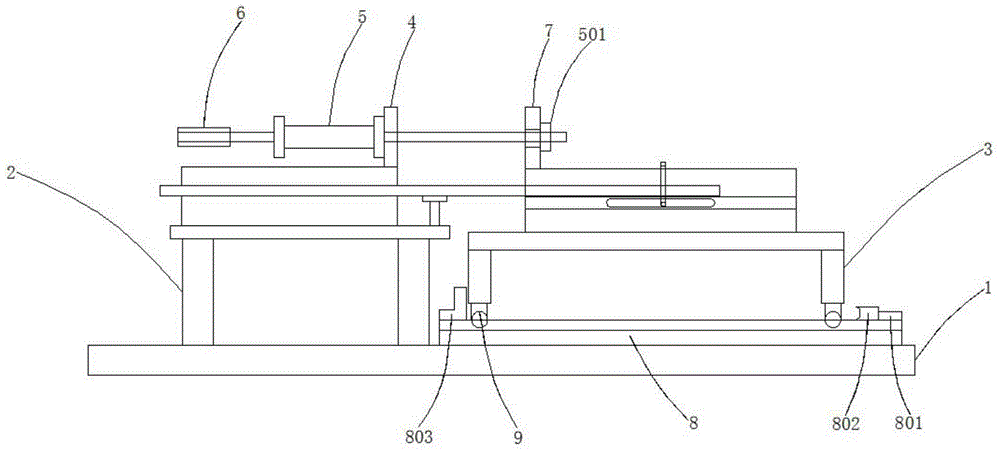
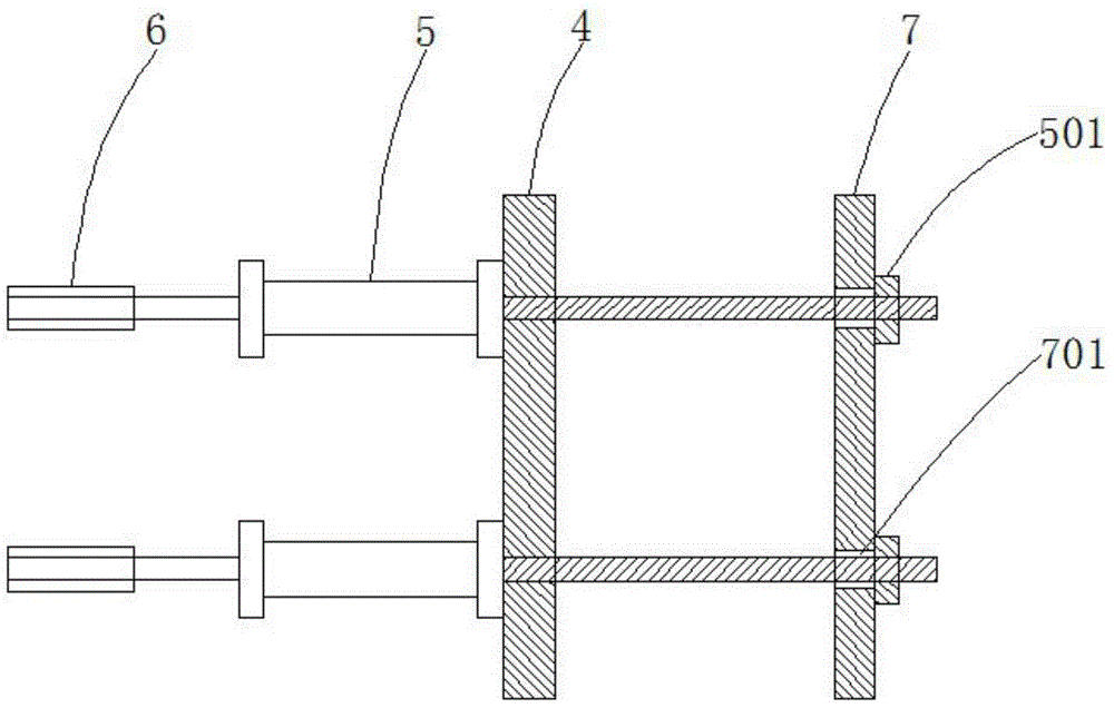
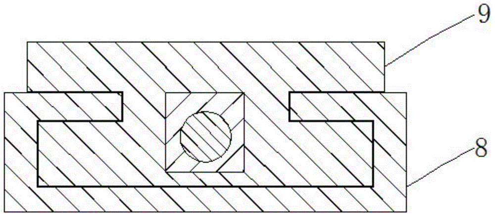

Image

  • Automatic moving device
  • Automatic moving device
  • Automatic moving device

Examples


Embodiment Construction

[0022] In the following, numerous specific details are set forth in order to provide a thorough understanding of the concepts underlying the described embodiments. It will be apparent, however, to one skilled in the art that the described embodiments may be practiced without some or all of these specific details. In other instances, well known processing steps have not been described in detail.

[0023] Such as figure 1 , figure 2 , image 3 As shown, it includes worktable 1, cooling machine 2, material receiving machine 3, cylinder fixing plate 4, cylinder 5, adjusting bolt 6, pushing plate 7, guide rail 8, slider 9, lock nut 501, mounting hole 701, The limit block 801, the buffer plate 802, the stop plate 803, the cylinder fixed plate 4 is located on the left side of the top of the cooling machine 2, and the two are connected with threads, and the cylinder 5 is located at the middle end of the left and right sides of the front of the cylinder fixed plate 4, and the two a...


PUM


Abstract

The invention discloses an automatic moving device which comprises a working table, a cooling machine, a receiving machine, an air cylinder fixing plate, air cylinders, adjusting bolts, a push plate, a guide rail and slide blocks, wherein the air cylinder fixing plate is located on the left side of the top end of the cooling machine and is in threaded connection with the cooling machine; the air cylinders are located at the middle ends on the left side and the right side of the front surface of the air cylinder fixing plate and are in threaded connection with the air cylinder fixing plate; the adjusting bolts are located at the tail ends of the air cylinders and are in threaded connection with the air cylinders; the pushing plate is located on the right side of the top end of the receiving machine and is in threaded connection with the receiving machine; the guide rail is located at the bottom of the receiving machine and is in threaded connection with the working table; and the slide blocks are located at the periphery of the bottom of the receiving machine and are in threaded connection with the receiving machine. The automatic moving device effectively avoids the problems of deviation and distance difference and greatly increases the production efficiency.

Description

technical field [0001] The invention relates to a mobile device, in particular to an automatic mobile device. Background technique [0002] With the rapid development of the economy, the application of plastic water pipes is becoming more and more popular. In the production process, in order to facilitate the production and splicing of water pipes of different specifications and lengths, it is often necessary to move the position of the splicing machine in a straight line. The traditional moving method is through the bottom of the splicing machine. Install casters to move, this method can not achieve accurate moving direction and moving distance, which will easily cause deviation and distance difference, resulting in poor material connection and even bending and damage of water pipes, seriously affecting production efficiency. In view of the above defects, it is necessary to design a An automatic mobile device. Contents of the invention [0003] The technical problem to b...

Claims


Application Information

Patent Timeline
Patent Type & Authority Applications(China)
IPC IPC(8): B23Q5/26F16C29/02F15B15/24
CPCB29D23/001B65G35/00B65G2201/0217F16C29/02
Inventor 毕强
Owner 安徽池州瑞强塑业有限公司
Learn More