Adjustable mould holder and powder forming and shaping machine with mould holder

A shaping machine and adjustable technology, which is applied in the field of formwork, can solve problems such as the error of metal powder rebound force, and achieve the effect of reducing processing cost, low processing cost and convenient operation

Active Publication Date: 2015-09-09
宁波汇众粉末机械制造有限公司
View PDF9 Cites 0 Cited by
  • Summary
  • Abstract
  • Description
  • Claims
  • Application Information

AI Technical Summary

Problems solved by technology

[0008] The first adjustment unit in the adjustable mold base of the present invention is used to solve the error caused by the processing accuracy of the mold base or the existence of the rebound force of the metal powder during the processing after the workpiece is formed once, resulting in the There is a small amount of height difference between the workpiece and the finished product during one forming, so the stroke of the mold base is s

Method used


Image

  • Adjustable mould holder and powder forming and shaping machine with mould holder
  • Adjustable mould holder and powder forming and shaping machine with mould holder
  • Adjustable mould holder and powder forming and shaping machine with mould holder

Examples


Embodiment 1

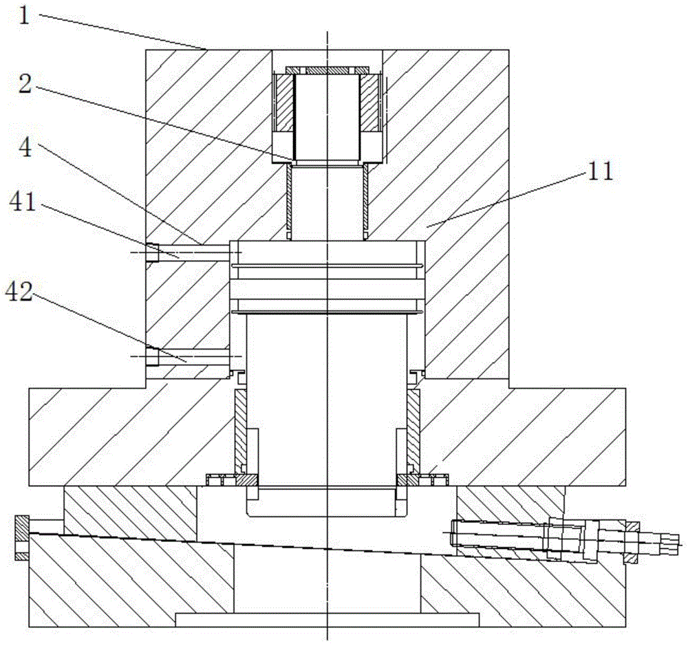
[0037] As the formwork described above, the present embodiment differs from it in that, see image 3 As shown, it is a structural schematic diagram of Embodiment 1 of the adjustable formwork in the present invention; the formwork also includes an oil delivery unit 4, and the oil delivery unit 4 includes a first oil pipe 41 and a second oil pipe 42 , the first oil pipe 41 and the second oil pipe 42 penetrate one side of the top stop plate 11, one end communicates with a hydraulic oil pump (not shown in the figure), and the other end communicates with the stroke unit 2 and the die The gap between the frame bracket 1 unit is used to adjust the stroke of the stroke unit 2, and also can reduce the friction between the stroke unit 2 and the mold frame bracket 1, prolong the service life of the mold frame, and It can buffer the impact force generated by the formwork during use, and also protect the formwork.

Embodiment 2

[0039] As the formwork described above, the present embodiment differs from it in that, see Figure 4 As shown, it is a schematic structural diagram of the second embodiment of the adjustable formwork in the present invention; the formwork also includes a second adjustment unit 5, a guide post 6 and a guide sleeve 7, wherein the second adjustment The unit 5 runs through the middle top plate 12 and the two upper punches 14, and is respectively fixed with the middle top plate 12 and the two upper punches 14, and the guide sleeve 7 is connected with the two upper punches 14. The guide post 6 passes through the middle top plate 12 , the two upper punches 14 and the guide sleeve 7 , and is fixed with the middle top plate 12 .

[0040] The second adjustment unit 5 includes a cover 51, a worm gear 52, a worm 53, a second piston rod 54, a first sleeve 55, a second sleeve 56, a first base 57, a second The base 58 and the base cover 59, wherein the cover 51, the first sleeve 55 and the...

Embodiment 3

[0043] As the formwork described above, the present embodiment differs from it in that, see Figure 5 As shown, it is a simple structural block diagram of powder forming and shaping machine in the present invention; and in combination Figure 6 As shown, it is a structural block diagram of the frame body described in the present invention; and Figure 7 As shown, it is a specific structural block diagram of the powder forming and shaping machine in the present invention; the powder forming and shaping machine also includes a frame body 8, and the frame body 8 is used to carry the mold base to complete the described Basic operation of powder molding and shaping machines. The frame body 8 includes a support 81, a female mold 82 and a forming mold frame 83, wherein one end of the female mold 82 is connected with the mold frame, and the other end is connected with the forming mold frame 83. connected for filling metal powder; the forming mold frame 83 is connected with the suppo...


PUM


Abstract

The invention provides an adjustable mould holder and a powder forming and shaping machine with the mould holder. The mould holder comprises a mould holder support, a stroke unit and a first adjustment unit; the stroke unit is connected with the mould holder support and is used in forming of a workpiece; and the first adjustment unit is connected with the mould holder support and is used to adjust stroke of the mould holder. The first adjustment unit in the adjustable mould holder is used to solve the problem of a micro height difference which exists between a workpiece while one-step forming and a finished product and which is resulted from machining precision of the mould holder or an error generated due to existing of a metal powder resilience force in a machining process after workpiece one-step forming, and the first adjustment unit finely adjusts the stroke of the mould holder in this way to enable a machining precision requirement to be achieved at the next time of workpiece forming. The structure of the first adjustment unit is simple, operation is convenient, and stability while workpiece stamping is high; and time for adjusting the stroke of the mould holder is short, rigidity is good, and reliability is good.

Description

technical field [0001] The invention relates to a mold base, in particular to an adjustable mold base and a powder forming and shaping machine with the mold base. Background technique [0002] The mold base is a bracket used to manufacture the mould. In the use of the mold base in the prior art, the structure of the mold to be formed is firstly adjusted, and then put into the powder forming machine to work. [0003] Please refer to the Chinese patent "A Cylinder with Adjustable Stroke", application number: 201210449520.1, the present invention discloses an oil cylinder with adjustable stroke, which includes a cylinder body, a cylinder head, a piston rod, a piston connected to the piston rod, and a rodless oil chamber. It is characterized in that there is a mounting seat fixedly connected to the front end of the cylinder body, and the mounting seat is provided with a worm screw and a worm gear meshing with the worm screw through a bearing, and a stroke positioning sleeve is p...

Claims


Application Information

Patent Timeline
IPC IPC(8): B22F3/03
Inventor 严培义严俏敏
Owner 宁波汇众粉末机械制造有限公司
Why Eureka
Try Eureka