Copper wire stator wire-hanging device

A technology of a copper wire stator and a rotating device, which is applied in the field of article racks, can solve the problems of low work efficiency, severe overhang of the shoulder of a large coil copper wire, deformation, etc., to prevent overhang and deformation, and improve the work efficiency of workers.

Inactive Publication Date: 2015-04-22
TIANJIN POLYTECHNIC UNIV
View PDF0 Cites 2 Cited by
  • Summary
  • Abstract
  • Description
  • Claims
  • Application Information

AI Technical Summary

Problems solved by technology

[0002] At present, the copper wire stator wire hanging device used in the production and assembly process of wind turbines, one is that one wire hanging device can only hang one set of copper wire stators at a time, workers need to frequently take copper wire stators, and the work effi

Method used


Image

  • Copper wire stator wire-hanging device
  • Copper wire stator wire-hanging device
  • Copper wire stator wire-hanging device

Examples


Embodiment Construction

[0011] The present invention will be further described in detail below in conjunction with the embodiments and accompanying drawings.

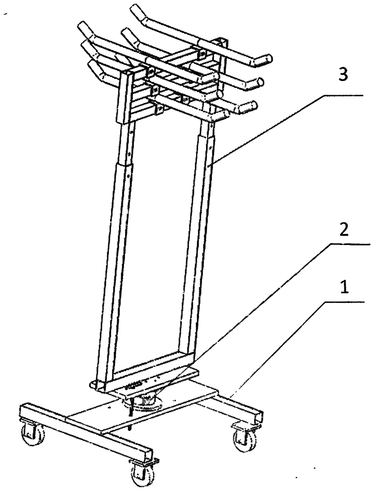
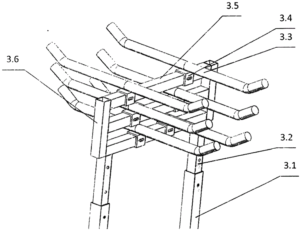
[0012] Such as figure 1 , figure 2 , image 3 As shown, the present invention provides a copper wire stator wire hanging device, which includes: a movable base 1, a rotating device 2, and a hanger 3;

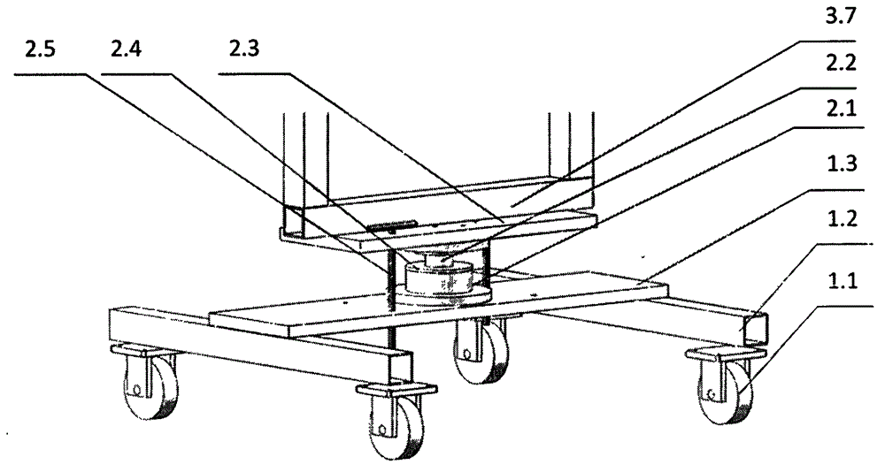
[0013] The movable base includes a bottom plate 1.3, a bottom beam 1.2, and a support wheel 1.1, the bottom plate 1.3 is fixed on the upper surface of the bottom beam 1.2 by welding, and the support wheel 1.1 is fixed on the lower surface of the bottom beam 1.2 by screwing;

[0014] The rotating device 2 includes a rotating shaft 2.2, a bearing seat 2.1, a bearing end cover 2.4, a connecting plate 2.3, and a latch 2.5. The bearing seat 2.1 is fixed on the upper surface of the base plate 1.3 through a threaded connection, and a bearing is installed on the lower end of the rotating shaft 2.2. The bearing is installed in the bearing seat 2.1, t...


PUM


Abstract

The invention discloses a copper wire stator wire-hanging device. The copper wire stator wire-hanging device comprises a movable base, a rotating device and a hanging rack.

Description

technical field [0001] The invention belongs to the field of object racks, in particular to a copper wire stator wire hanging device used in the assembly process of a wind power generator. Background technique [0002] At present, the copper wire stator wire hanging device used in the production and assembly process of wind turbines, one is that one wire hanging device can only hang one set of copper wire stators at a time, workers need to frequently take copper wire stators, and the work efficiency is relatively low; two It is because all the copper wires are hung on two hanging rods at a fixed distance, which cannot adapt to copper wires of different coil sizes, causing the shoulders on both sides of the large coil copper wires to hang severely and seriously deformed. Contents of the invention [0003] Aiming at the deficiencies of the prior art, the technical problem to be solved by the present invention is to provide a copper wire stator wire hanging device, which incl...

Claims


Application Information

Patent Timeline
IPC IPC(8): B25H3/04
CPCB25H3/04
Inventor 李皎李斧头王艺林环宇
Owner TIANJIN POLYTECHNIC UNIV
Why Eureka
Try Eureka