
Time delay and integration scanning using a CCD imager

A technology of time-delay integration and integration lines, applied in the field of image scanning

Active Publication Date: 2015-04-22
THORLABS INC
View PDF6 Cites 8 Cited by
  • Summary
  • Abstract
  • Description
  • Claims
  • Application Information

AI Technical Summary

Problems solved by technology

However, this solution has significant limitations, including a long minimum exposure duration of approximately 120 ms and a fixed, very large TDI shift

Method used


Image

  • Time delay and integration scanning using a CCD imager
  • Time delay and integration scanning using a CCD imager
  • Time delay and integration scanning using a CCD imager

Examples


Embodiment Construction

[0024] The description of illustrative embodiments in accordance with the principles of the invention is intended to be read in conjunction with the accompanying drawings, which are considered a part of this entire written description. In the description of the disclosed embodiments of the invention, reference to any direction or orientation is for convenience of illustration only and is not intended to limit the scope of the invention in any way. Relative terms (e.g., "lower", "upper", "horizontal", "vertical", "above", "below", "upward", "downward", "top", and "bottom") and their derivatives (eg, "horizontally," "downwardly," "upwardly," etc.) should be construed in the orientations described below or shown in the figures in question. These relative terms are used for convenience of description only and do not require the equipment to be constructed or operated in a particular orientation unless expressly stated otherwise. Unless expressly stated otherwise, terms such as "a...


PUM


Abstract

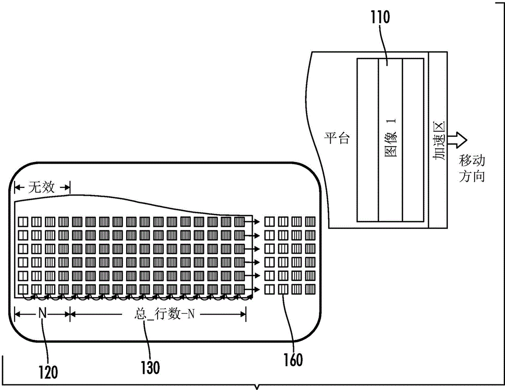
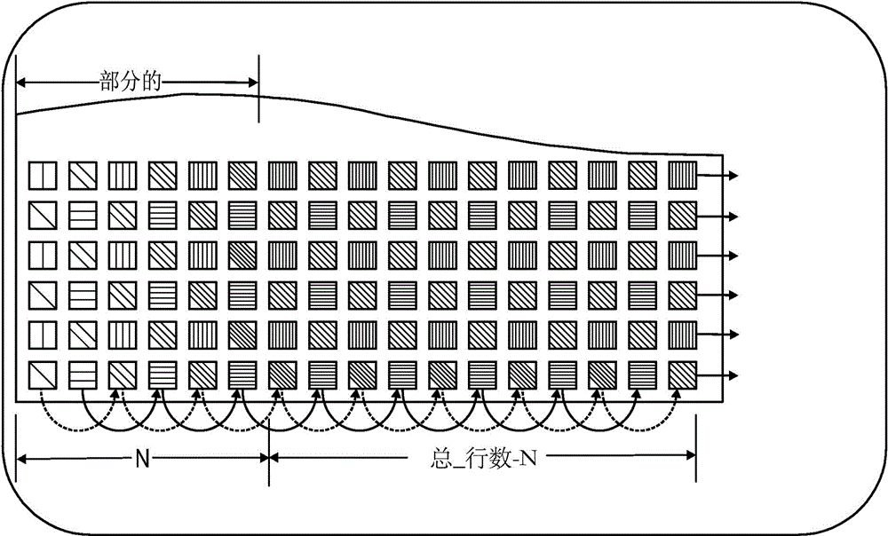
A method for operating a focal plane array in a Time Delay Integration (TDI) mode, the method including: shifting a number of rows during TDI integration, wherein the number of rows shifted is less than a total number of rows of the focal plane array; and reading out a number of rows equal to the total number of rows of the focal plane array minus the number of rows shifted, leaving behind the partially-integrated rows.

Description

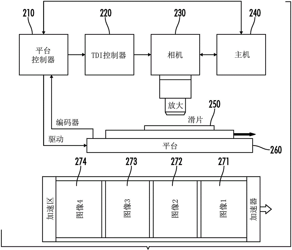
[0001] Cross References to Related Applications [0002] This application claims priority to US Provisional Patent Application Serial No. 61 / 713,474, filed October 12, 2012, the contents of which are hereby incorporated by reference. technical field [0003] The invention relates to the field of image scanning, in particular to time delay and integration (TDI) scanning using a CCD imager. Background technique [0004] Interline CCD imagers can be operated in TDI mode, for example, as defined in U.S. Patent 4,922,337, as in conventional TDI cameras to expose moving objects in non-stop motion, while also performing conventional video Live or take long exposures of stationary objects that are not practical with traditional TDI cameras. So, for example, it is possible to scan a large area at high speed by continuing to move, and then return to a very small, high-magnification, stationary region of interest with the same camera and equipment. [0005] When the inter-row CCD ope...

Claims


Application Information

Patent Timeline
Patent Type & Authority Applications(China)
IPC IPC(8): H04N5/335H04N5/3728H04N25/00H04N25/46H04N25/73
CPCH04N5/37206H04N5/37213H04N5/353H04N25/711H04N25/713H04N25/53
Inventor M·帕克J·米尔斯A·帕巴拉F·阿姆斯特朗J·埃里克森G·黑文加C·泰勒W·拉特德克
Owner THORLABS INC
Learn More