OCT (Optical Coherence Tomography) imaging system and method for monitoring shaping effect of orthokeratology lens by using living body

An orthokeratology lens and imaging system technology, applied in the field of medical testing, can solve the problems of inability to monitor the effect of orthokeratology, large errors, and inability to represent the fit state.

Active Publication Date: 2015-04-29
维视艾康特(广东)医疗科技股份有限公司 +1
View PDF8 Cites 14 Cited by
  • Summary
  • Abstract
  • Description
  • Claims
  • Application Information

AI Technical Summary

Problems solved by technology

Although this is a good lens fitting software, because it is based on a complete mathematical simulation, it will also be affected by the quality, quantity, and eyelid tension of tear secretion in actual application, so it cannot represent the actual fitting state
In addition, the Ortho Tool only reflects the situation of one meridian. In the case of asymmetric butterflies, or poor corneal regularity and symmetry, the error may be even greater
The main disadvantage is that the above method does not quantitatively evaluate the transition zone between the most critical base arc and reversal arc, so it is impossible to dynamically monitor the corneal shaping effect.

Method used


Image

  • OCT (Optical Coherence Tomography) imaging system and method for monitoring shaping effect of orthokeratology lens by using living body
  • OCT (Optical Coherence Tomography) imaging system and method for monitoring shaping effect of orthokeratology lens by using living body
  • OCT (Optical Coherence Tomography) imaging system and method for monitoring shaping effect of orthokeratology lens by using living body

Examples


Embodiment Construction

[0024] Embodiments of the present invention will be further described below in conjunction with accompanying drawings:

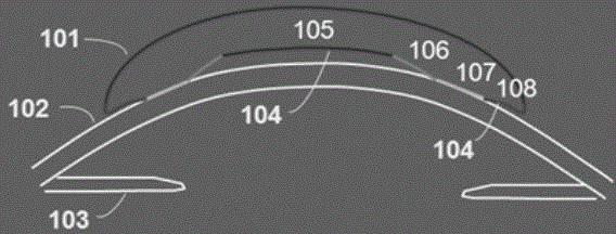
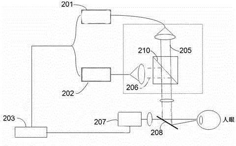
[0025] Such as figure 2As shown, the present invention provides: an OCT imaging system for monitoring the shaping effect of orthokeratology lenses in vivo, which includes a control computer 203, a spectral domain OCT imaging module, a human eye scanning module, and an optotype alignment module 207. The computer 203 is respectively connected with the spectral domain OCT imaging module and the visual mark alignment module 207, and the human eye scanning module is located on the optical path between the spectral domain OCT imaging module and the visual mark alignment module, and the spectral domain OCT imaging module It includes a full-view spectral domain OCT imaging module 202 and a partial spectral domain OCT imaging module 201, and a movable 45° beam splitter 210 is arranged between the optical paths of the full-view spectral domain OCT imaging module 202 ...


PUM


Abstract

The invention relates to an OCT (Optical Coherence Tomography) imaging system and a measurement method for monitoring the shaping effect of an orthokeratology lens by using a living body, wherein the OCT imaging system comprises a control computer, a spectral-domain OCT imaging module, a human eye scanning module and an optotype aligning module; the spectral-domain OCT imaging module comprises a partial spectral-domain OCT imaging module and a full spectral-domain OCT imaging module; a movable 45-degree spectroscope is arranged between the partial spectral-domain OCT imaging module and the full spectral-domain OCT imaging module. The measurement method comprises the following steps of (1) obtaining a full orthokeratology image of a living body; (2) obtaining an actual lens thickness contour image; (3) analyzing the center positioning state of the whole orthokeratology lens; (4) obtaining a partial high-definition image of the orthokeratology lens, and obtaining the length, width and area of a transition region. According to the OCT imaging system and the measurement method for monitoring the shaping effect of the orthokeratology lens by using the living body, the orthokeratology image of the living body and the partial orthokeratology image in a feature region are analyzed, the transition region of the orthokeratology lens is directly imaged, and a purpose of dynamically monitoring the cornea flattening progress and the cornea shaping effect according to the dynamic variation of a tear film along with time is achieved.

Description

technical field [0001] The invention relates to an OCT imaging system and method for monitoring the shaping effect of an orthokeratology lens in a living body, and belongs to the technical field of medical detection. Background technique [0002] The prevalence of myopia in China is about 32.3%, which is one of the countries with the highest incidence of myopia in the world. In addition to causing vision loss, pathological myopia can also cause complications such as retinal detachment, macular hemorrhage, retinal atrophy, macular degeneration, vitreous opacity, and lens opacity. In severe cases, it can even cause complete loss of vision. Therefore, the prevention and control of myopia is an important task without delay. Orthokeratology lenses are currently one of the effective ways to temporarily reduce the degree of myopia, but the fitting problem that always plagues the orthokeratology effect is the central positioning of orthokeratology lenses. Literature research shows...

Claims


Application Information

Patent Timeline
Patent Type & Authority Applications(China)
IPC IPC(8): A61B3/14
Inventor 沈梅晓陶爱珠吕帆袁一民姜珺
Owner 维视艾康特(广东)医疗科技股份有限公司
Why Eureka
Try Eureka