Drainage bag

A drainage bag and liquid technology, applied in the field of drainage bag, can solve the problem of inconvenient and accurate observation of drainage liquid or gas

Inactive Publication Date: 2015-04-29
SUZHOU UNIV
View PDF8 Cites 1 Cited by
  • Summary
  • Abstract
  • Description
  • Claims
  • Application Information

AI Technical Summary

Problems solved by technology

[0004] It can be seen that in the drainage bag disclosed in the above prior art, liquid and gas are mixed and stored in the main body of the drainage bag, which is not convenient for medical staff to accurately observe the amount of drainage liquid or gas

Method used


Image

  • Drainage bag

Examples


Embodiment Construction

[0019] The technical solutions in the embodiments of the present invention will be described in detail below in conjunction with the accompanying drawings.

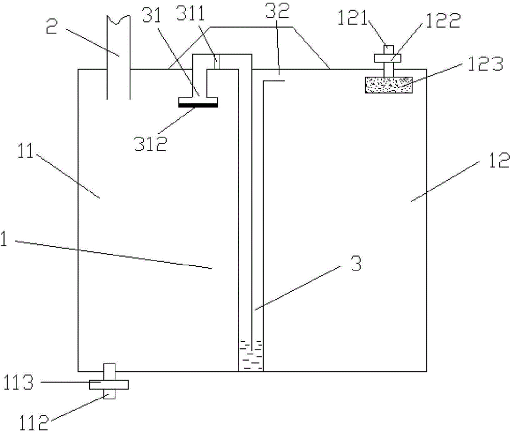
[0020] Such as figure 1 As shown, the present invention discloses a drainage bag, which includes a drainage bag body 1, and a connecting tube 2 is arranged above the drainage bag body 1. When in use, the connecting tube 2 is connected with the anal canal or other drainage tubes placed in the patient's body.

[0021] In the traditional drainage bag, the liquid and gas drained from the anal canal or other drainage tubes placed in the patient's body are mixed and stored in the drainage bag body 1, which is not convenient for medical staff to accurately observe the amount of drainage liquid or gas. Therefore, the drainage bag disclosed in the present invention also includes a gas-liquid separation device 3, and the gas-liquid separation device 3 separates the drainage bag body 1 into two parts, a liquid storage part 11 and a ...


PUM


Abstract

A drainage bag comprises a bag body, the upper portion of the bag body is provided with a connecting tube, the drainage bag further comprises a gas-liquid separator, the gas-liquid separator divides the bag body into a liquid storage portion and a gas storage portion, the liquid storage portion is used for storing liquid, the gas storage portion is used for storing gas, and the connecting tube is arranged above the liquid storage portion. By dividing the bag body into the liquid storage portion used for storing the liquid and the gas storage portion used for storing the gas, the gas and the liquid are separately drained, and medical staff is allowed to accurately observe the volume of drained liquid or gas.

Description

technical field [0001] The invention relates to the technical field of medical supplies, in particular to a drainage bag. Background technique [0002] Drainage is an operation often required in clinical practice. For example, after general surgery of the abdominal cavity, it is often necessary to place a drainage tube to drain the effusion or air accumulation in the wound cavity. In critically ill patients, especially those with fecal incontinence or who require observation of anal exhaust, an anal canal is often placed to drain large bowel contents such as thin stool and gas. The current drainage bags are usually mainly for drainage of liquid, and some drainage bags are designed to drain gas, but they are limited to the mixed drainage of gas and liquid, making it impossible to accurately observe the amount of drainage liquid or gas during the drainage process. [0003] For example, the Chinese utility model patent published on October 15, 2014, the patent application numb...

Claims


Application Information

Patent Timeline
IPC IPC(8): A61M1/00
CPCA61M1/69
Inventor 王丽胡化刚
Owner SUZHOU UNIV
Why Eureka
Try Eureka