Hydraulic module for transmission

A hydraulic module and gearbox technology, which is applied to components with teeth, belts/chains/gears, mechanical equipment, etc., can solve problems that affect the shifting effect and cannot be controlled independently, so as to improve safety and reliability. Protect the mechanical structure and retain the effect of the control effect

Active Publication Date: 2017-01-18
UNITED AUTOMOTIVE ELECTRONICS SYST
View PDF5 Cites 0 Cited by
  • Summary
  • Abstract
  • Description
  • Claims
  • Application Information

AI Technical Summary

Problems solved by technology

However, because the oil pressures of the two clutches are interrelated, they cannot be controlled independently, which affects the effect of shifting gears.

Method used


Image

  • Hydraulic module for transmission
  • Hydraulic module for transmission
  • Hydraulic module for transmission

Examples


Embodiment Construction

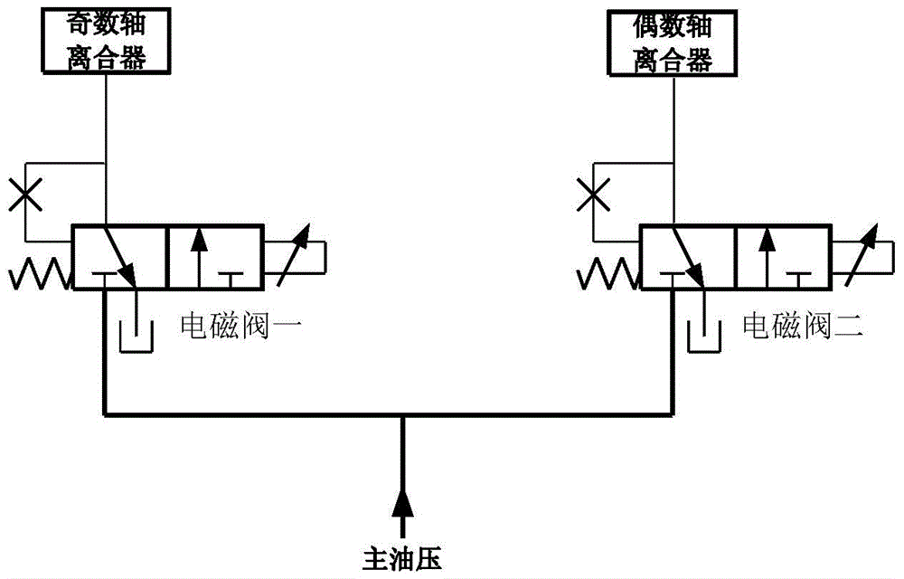
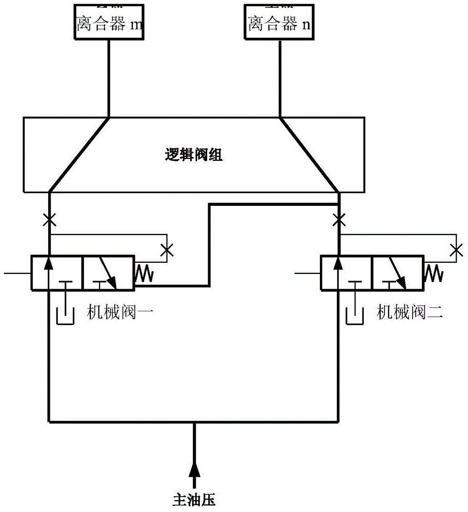
[0023] see image 3 , which is the hydraulic module of the gearbox of the present application, applicable to DCT or AT (if used for AT, the odd shaft clutch and the even shaft clutch should be changed to clutch m and clutch n). The shifting mechanism is jointly controlled by four electromagnetic valves and four mechanical valves and two clutches. The four solenoid valves are two proportional valves and two on-off valves, all of which are controlled by the TCU. The thick solid line indicates that there is a certain oil pressure in the oil circuit, and the thin solid line indicates that the oil pressure in the oil circuit is zero.

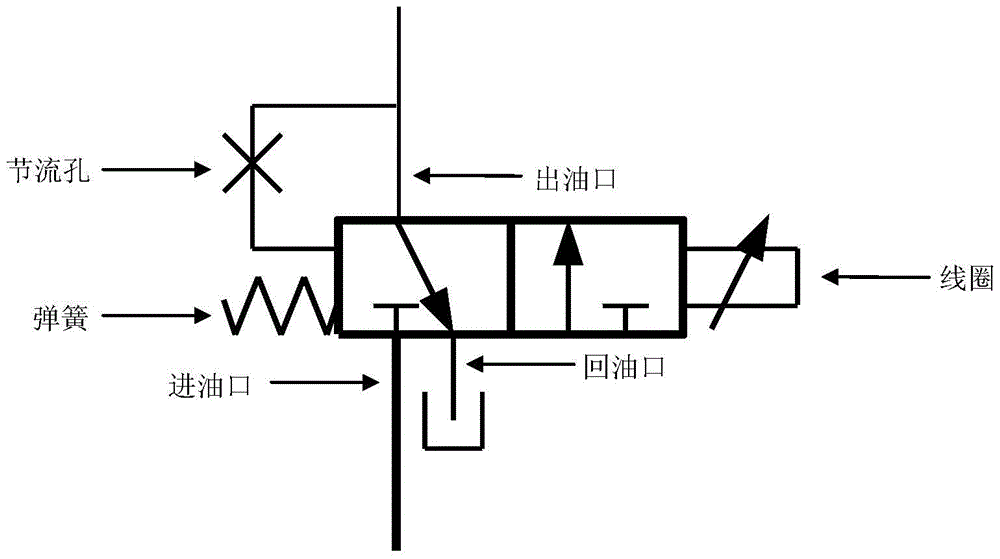
[0024] The proportional valve is as Figure 1a The two-position three-way solenoid valve shown, the two positions refer to the oil unloading state from the oil outlet to the oil return port, and the oil delivery state from the oil inlet to the oil outlet. The proportional valve can realize the oil pressure of the oil outlet. continuous adjustment....


PUM


Abstract

The invention discloses a hydraulic mold of a speed changing box. A main oil pressure pipeline is connected with the oil inlets of four electromagnetic valves, a first mechanical valve and a second mechanical valve; the oil outlet of a first proportional valve is connected with the left-side oil inlet and the spring opposite side of a third mechanical valve; the oil outlet of a second proportional valve is connected with the right-side oil inlet and the spring opposite side of a fourth mechanical valve; the oil outlet of a first switching valve is connected with the spring side of the first mechanical valve; the oil outlet of a second switching valve is connected with the spring side of the second mechanical valve; the oil outlet of the first mechanical valve is connected with the right-side oil inlet and the spring side of the third mechanical valve; the oil outlet of the second mechanical valve is connected with the oil outlet and the spring side of the fourth mechanical valve; the oil outlet of the third mechanical valve is connected with the other clutch and the spring opposite side of the second mechanical valve; the oil outlet of the fourth mechanical valve is connected with another clutch and the spring opposite side of the first mechanical valve. The hydraulic mold of the speed changing box is capable of the case of dual locking of the shaft system of the two clutches, and meanwhile, does not intervene with independent control on the two clutches by use of a TCU within a safety threshold.

Description

technical field [0001] The present application relates to a gearbox for shifting through two clutches, and in particular to a hydraulic module therein. Background technique [0002] Gearboxes that shift gears by switching between two clutches include dual-clutch gearboxes (DCT) and automatic transmissions (AT). The technical difficulty lies in the control of the two clutches during the gearshift process. Take the DCT as an example, it has two clutches, one clutch is disengaged while the other clutch is engaged when shifting gears. Take the AT as an example, it has multiple clutches (and brakes), only two clutches act during sequential gear shifting, and one clutch is disengaged while the other clutch is engaged. [0003] see figure 1 , which is a non-complete hydraulic module of the existing DCT, also applies to the AT. The hydraulic module controls two clutches respectively by two solenoid valves 1 and 2 which are independent of each other. The thick solid line indicate...

Claims


Application Information

Patent Timeline
Patent Type & Authority Patents(China)
IPC IPC(8): F16H61/12F16H61/02
CPCF16H61/12F16H61/40
Inventor 王宇明张宽宽杨庆江兴宏殷孝龙李淑英邹绵意王治松
Owner UNITED AUTOMOTIVE ELECTRONICS SYST
Why Eureka
Try Eureka