Liftable power generator assembly with automatic braking function

An automatic braking and generator technology, applied in the direction of brakes, braking components, mobile frames, etc., can solve the problems of collision damage to the main equipment, increase the overall equipment volume, increase the complexity, etc., to avoid collision damage, practical Strong performance, simple and compact structure

Inactive Publication Date: 2015-04-29
LONCIN MOTOR
View PDF7 Cites 0 Cited by
  • Summary
  • Abstract
  • Description
  • Claims
  • Application Information

AI Technical Summary

Problems solved by technology

[0003] In the prior art, since this type of generator is generally small, the traveling wheels are made smaller, and the passing capacity after being installed at the bottom of the frame is relatively poor; and, due to the small traveling wheels, the ground clearance of the frame is small when walking, so it is not easy to Smooth passing conditions can cause collision damage to the main equipment
At the same time, when the existing generator is working, it is necessary to brake the traveling wheels, so a set of braking mechanism needs to be installed, which increases the volume of the overall equipment and increases the complexity; the operation is also relatively inconvenient

Method used


Image

  • Liftable power generator assembly with automatic braking function
  • Liftable power generator assembly with automatic braking function

Examples


Embodiment Construction

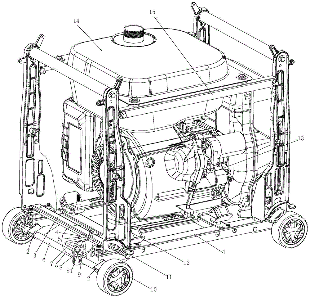
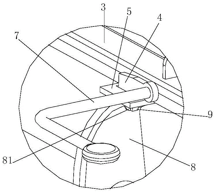
[0022] figure 1 It is a structural schematic diagram of the present invention, figure 2 for figure 1 The enlarged view at A, as shown in the figure: the liftable generator assembly with automatic braking in this embodiment includes main equipment and a rack assembly for installing the main equipment; the rack assembly includes a walking The wheel assembly and the bottom plate 1 used to install the main equipment, the bottom 1 plate is supported on the road wheel assembly through the lifting mechanism; the brake plate is installed on the frame, and the brake plate is from the radial outer edge from top to bottom Facing the walking rotating part of the walking wheel assembly, and the brake plate 11 brakes the rotating part when the base plate 1 is at a low point; the walking wheel assembly generally includes the walking wheel and the mounting parts, which will not be described in detail here; the lifting mechanism can be an existing Some ball screw mechanisms, casing mechanis...


PUM


Abstract

The invention discloses a liftable power generator assembly with an automatic braking function, comprising main equipment, and a frame assembly which is used for installing the main equipment, wherein the frame assembly comprises a walking wheel component, and a bottom plate which is used for installing the main equipment; the bottom plate is supported at the walking wheel component through a lifting mechanism; a braking plate is arranged on a frame; the braking plate directly faces to a walking rotation member of the walking wheel component from top to bottom from the radial edge; the braking plate brakes the rotation member when the bottom plate is positioned in a low point. According to the liftable power generator assembly with the automatic braking function, the bottom plate, which is used for installing the main equipment, is manufactured into a liftable structure, a braking effect or a releasing effect is automatically formed along with the action of the liftable structure, and the lifting operation is performed according to walking and use demands; the braking plate forms the braking effect by means of descending when the bottom plate descends to the lowest point for working; the liftable power generator assembly with the automatic braking function has the advantages that the structure is simple and compact, the practicability is strong, an independent braking structure is unnecessary, a better through capacity is obtained in the transportation process, and a ground clearance of the frame is increased, so that the ground clearance of the main equipment is guaranteed, and damage caused by the collision in the walking process is prevented.

Description

technical field [0001] The invention relates to a power generating equipment, in particular to a liftable generator assembly with automatic braking. Background technique [0002] Small general-purpose machinery has a small volume and weight, and is widely used; for example, small general-purpose generators are widely used in family life and other fields due to their small size and compact structure; generally including main equipment and racks, for the convenience of movement , Generally, road wheels are installed under the frame, and when in fixed use, the road wheels are braked. [0003] In the prior art, since this type of generator is generally small, the traveling wheels are made smaller, and the passing capacity after being installed at the bottom of the frame is relatively poor; and, due to the small traveling wheels, the ground clearance of the frame is small when walking, so it is not easy to Smooth passing conditions can cause collision damage to the subject equip...

Claims


Application Information

Patent Timeline
Patent Type & Authority Applications(China)
IPC IPC(8): F16M3/00B60B33/06F16D71/00B60T1/04
Inventor 张晓川王小勇张清詹文顶谢育明王婷田辉武自强周智超
Owner LONCIN MOTOR
Why Eureka
Try Eureka