Power assembly mounting structure

A powertrain and installation structure technology, applied in the direction of power plant, superstructure, substructure, etc., can solve the problems of cost increase

Inactive Publication Date: 2007-09-26
MITSUBISHI MOTORS CORP +1
View PDF8 Cites 0 Cited by
  • Summary
  • Abstract
  • Description
  • Claims
  • Application Information

AI Technical Summary

Problems solved by technology

However, the use of materials with high specific strength will increase the cost

Method used


Image

  • Power assembly mounting structure
  • Power assembly mounting structure
  • Power assembly mounting structure

Examples


Embodiment Construction

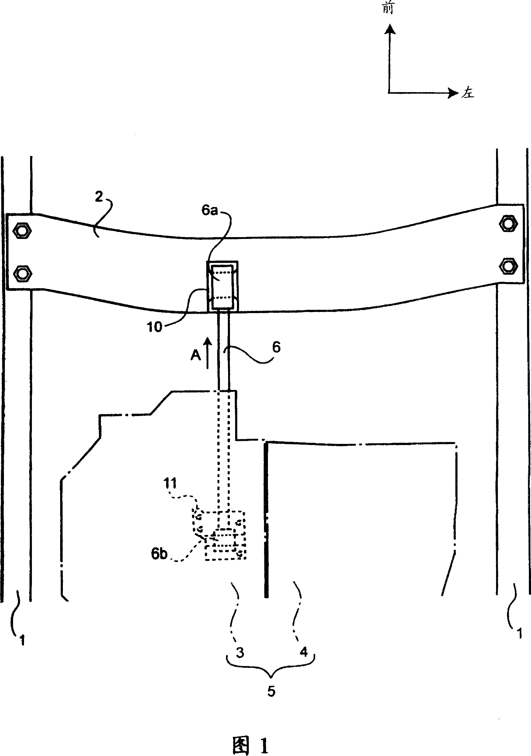
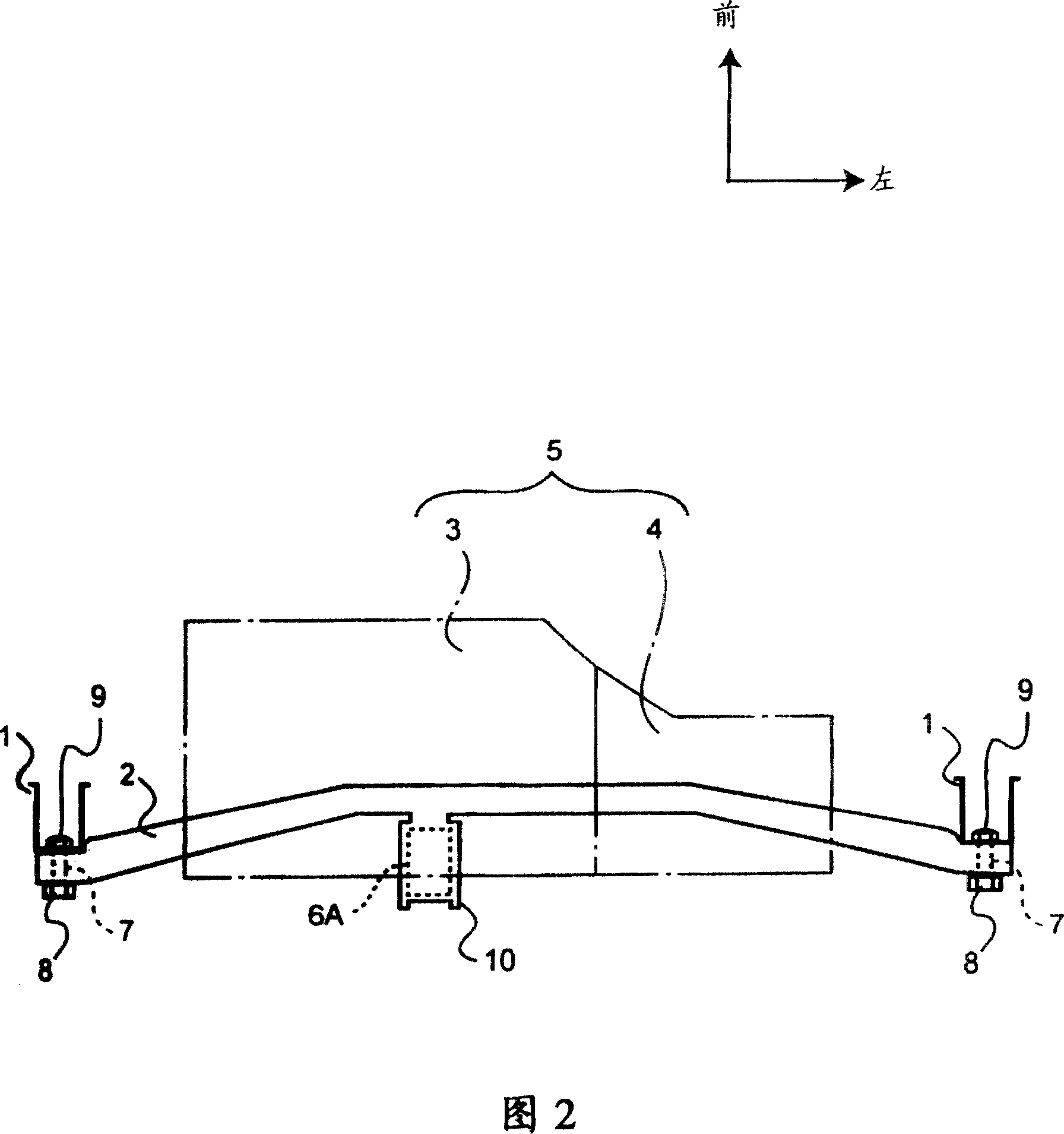
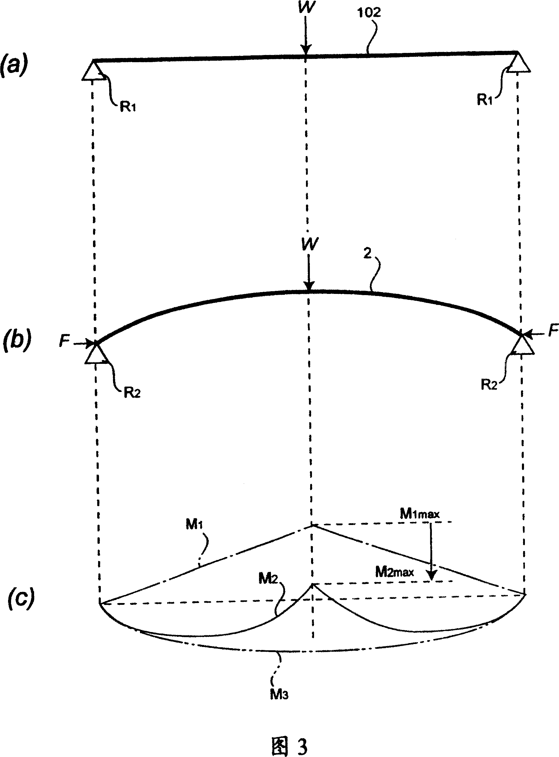
[0015] Referring to FIGS. 1 to 3 , a powertrain mounting structure according to the present invention will be described hereinafter. Fig. 1 is a plan view schematically showing the installation structure of the powertrain, Fig. 2 is a front view of the installation structure of the powertrain, and Fig. A schematic diagram of the state.

[0016] As shown in FIG. 1 , a pair of side beams 1 and 1 extend in the longitudinal direction of the vehicle, and a cross beam 2 is arranged in the transverse direction of the vehicle, and both ends of the cross beam are fixed to the aforementioned side beams 1 and 1 . Furthermore, a powertrain 5 composed of an engine 3 and a transmission 4 is located between the right side beam 1 and the left side beam 1 and behind the cross beam 2 . Furthermore, an anti-sway bar (rod) 6 is arranged between the crossbeam 2 and the powertrain 5 , thereby establishing a connection between the powertrain 5 and the crossbeam 2 .

[0017] In this structure, as s...


PUM


Abstract

The present invention relates to a power plant unit mounting structure for mounting a power plant unit, including an engine and a transmission, on a vehicle. The power plant unit mounting structure comprises a pair of side frames disposed in longitudinal direction of the vehicle, a cross member fixed at its both ends to the side frames to be disposed between the pair of side frames in lateral direction of the vehicle, and a rod disposed to make a connection between the power plant unit and the cross member. The cross member is shaped into a convex configuration curved against a direction of a load inputted via the rod. Therefore, the cross member can display a sufficient rigidity to be bearable against a load inputted from the power plant unit.

Description

technical field [0001] The present invention relates to a power assembly mounting structure suitable for mounting a power assembly, such as an engine, on a vehicle. Background technique [0002] Generally, in a vehicle, an engine and a transmission (they will be collectively referred to as "power assembly" hereinafter) are fixedly connected to the vehicle body through elastic members, such as mounting pieces, and the vehicle body includes a pair of beams extending longitudinally of the vehicle, with Beams and other members connecting between the pair of side beams. A technique disclosed in Japanese Registered Utility Model No. 2578792 is known as an example of a general structure for mounting a powertrain on such a vehicle. [0003] However, the powertrain is subject to vibration or oscillation during operation, and for this reason, members for mounting the powertrain need to be rigid to withstand loads resulting from such vibration or oscillation. In this case, although a...

Claims


Application Information

Patent Timeline
Patent Type & Authority Patents(China)
IPC IPC(8): B60K5/06B62D21/00B62D25/20B60K5/04B60K5/12
CPCB60K5/12
Inventor 黑川博幸黄田义则
Owner MITSUBISHI MOTORS CORP
Why Eureka
Try Eureka